 桥梁外文翻译

《桥梁外文翻译》由会员分享,可在线阅读,更多相关《桥梁外文翻译(28页珍藏版)》请在装配图网上搜索。
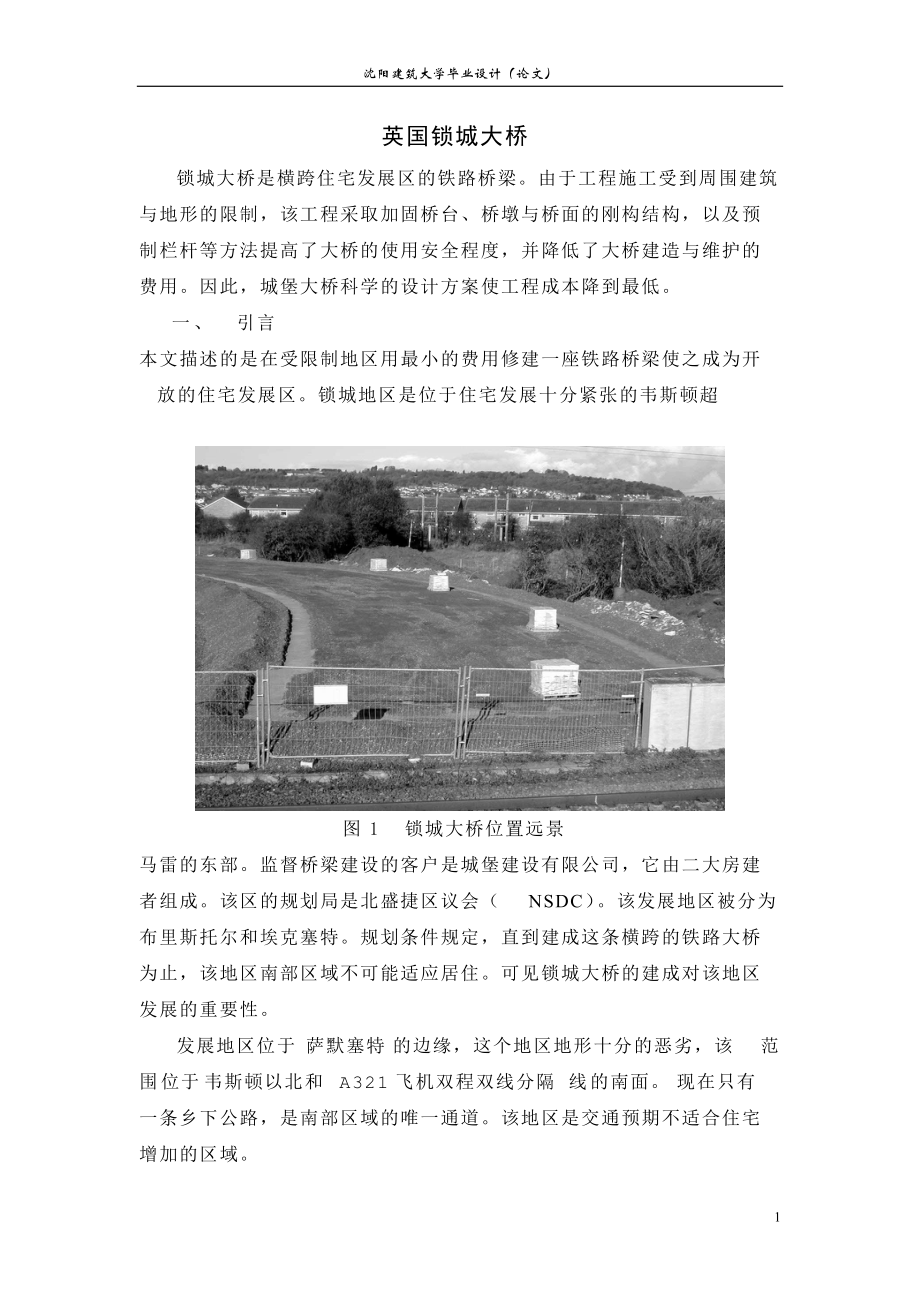
1、沈阳建筑大学毕业设计(论文)英国锁城大桥锁城大桥是横跨住宅发展区的铁路桥梁。由于工程施工受到周围建筑与地形的限制,该工程采取加固桥台、桥墩与桥面的刚构结构,以及预制栏杆等方法提高了大桥的使用安全程度,并降低了大桥建造与维护的费用。因此,城堡大桥科学的设计方案使工程成本降到最低。一、 引言本文描述的是在受限制地区用最小的费用修建一座铁路桥梁使之成为开放的住宅发展区。锁城地区是位于住宅发展十分紧张的韦斯顿超图1 锁城大桥位置远景马雷的东部。监督桥梁建设的客户是城堡建设有限公司,它由二大房建者组成。该区的规划局是北盛捷区议会(NSDC)。该发展地区被分为布里斯托尔和埃克塞特。规划条件规定,直到建成这
2、条横跨的铁路大桥为止,该地区南部区域不可能适应居住。可见锁城大桥的建成对该地区发展的重要性。发展地区位于萨默塞特的边缘,这个地区地形十分的恶劣,该范围位于韦斯顿以北和A321飞机双程双线分隔线的南面。现在只有一条乡下公路,是南部区域的唯一通道。该地区是交通预期不适合住宅增加的区域。由于盛捷地区水平高程的限制,新的铁路线在桥台两边必须设有高程差。 并且该地区地形限制,允许正常横跨的区域较小,这导致在结构的布局上的一定数量的妥协。为了整个城堡地区的发展, 全图2 锁城大桥地图上位置桥限速20公里/时,并考虑区域范围内的速度制约。这样在得到客户和NSDC的同意后,桥梁采取了最小半径的方法,这使得桥梁
3、采用了比正常梯度更加陡峭地方法实现高程的跨越。客户的工程师、工程顾问、一般设计原则和初步认同原则下(AIP)与NSDC发出投标文件。该合同在2000年7月1授予安迪。投标价值1.31亿美元,合同期定为34周,到2001年4月完成。 图3 桥整体横断面 图4 桥体长度 图5 桥上部结构横断面二、地基在招标阶段佩尔研究了一些优化设计和招标后的裁决计划进行了充分的经济分析后交付承包商,院长及安迪 。原来设计要求H型图6 桥面铺装钢桩柱下的桥台地区与相邻铁路线之间必须是垂直运动。经审查后的地面条件和根据以往的经验判断,现浇位移桩,使用其他类似地方的河堤下,可驱动更接近轨道而不会有任何问题。并在受影响区
4、域进行了监测,打桩作业和水平高程的变化小于要求的6毫米。在地面下覆盖厚达19米的软冲积土。这下面是2米层坚定/硬粘土泥岩或砂岩基石。两种类型的驱动现浇桩设计了340和380毫米的大口径水管,以应付不同载入条件所造成的桥梁和堤坝的不同荷载。 这些有利于桩体的载入。最多可达一天8个桩的记录。总长度驱动介于22和24米之间。试验证实了完整的设计和表示最多解决在工作负荷为六毫米一个具体的桩帽负载从桥墩传递到桩。 取代H型桩柱与 驱动现浇桩, 但略有减少水,它能使桩帽的荷载延长传递到承台,从而节约施工时间 以及成本。三、荷载传递,路基桩被用来抑制端口的负载转移,这是因为修建时采用了石头和网膜。 在招标图
5、纸上显示了基础顶部扩大桩,再运用早先经验, 佩尔指出这个设计方法可能被运用减少垫层的深度,并且把这种方法使用在城堡大桥上。 通过熔铸一个扩大的部分1.1m在每桩上面,距离到桩下减少了1 m直径,并且薄膜的间距在垫层的增加因而被减少了。 假设成拱形的作用在承台依靠角度458从堆到垫层的上面,可能相应地减少石头的深度。通过合理的设计,垫层的整体深度从1500毫米减少了到900毫米。 这样减少了挖掘深度并保留了原始的底层。.垫层路堤上升到最大高度6.3 m的车道高程。为了减少蔓延的路堤,招标设计最初面临混凝土预制板垂直侧壁。这是后来修正的在投标阶段用红砖砌筑的垂直墙壁,迫使改变设计中的钢筋路堤。路基
6、被分包两个部分以坦萨为基础和规范发展的佩尔弗里斯赫曼恩路段。其系统组成的单轴土工格栅在不同规定垂直间隔的压实颗粒物质。颗粒状材料,符合高速公路规范做路堤材料的相关规定。该网格,挂靠在干燥的混凝土砌块上形成近垂直的路堤。被垂直排水层分开。在两者之间安装了隔水带,并且在前面修建了砖砌饰面。 图-4展示基础的横断面。 图7 防撞墙路堤的设计是依靠紧密的产品的密度结构。这并不会减少桥梁结构的120年的设计使用寿命。此方法的约束结构是众所周知的, 并且在结算梁末端的负弯矩时作为一个统一体来解决。并且利用墩台的内力来约束其相对移动。在招标图纸上还限制了必须要保持同样的深度。现在 从Y3到Y4进行简化设计,
7、这样就会有更高的桥基、更大的桩和桥梁荷载,造成进口的材料损失。院长及安迪在这一共同目标下进行了这项工作。净厚40毫米的沥青混凝土不仅满足材料等级的要求,也适合使用在负荷传递的垫层上。此外,一直在现场进行永久材料的测试,而在兴建河堤时,该材料很容易压实,按要求使用1.5吨的振动压路机碾压,而且,就其性质而言,非常适合埋设在潮湿的条件。所有的测试结果显示, 最低的压实度在94 以上,压实度远远超过承包商期望。四、桥梁和桥墩桥面包括预制预应力混凝土梁和一块跨度20m的现浇钢筋混凝土平板。图4和5显示桥梁的长度和横断面。 在加强的桥台建立支撑梁。在支撑梁区域凸显了桥台狭窄的特点,并且这些太狭窄的桥台图
8、8 挡土墙不能避免的退出工作结构,并对混凝土砌块侧壁的河堤产生压力。为了克服这个困难,把河堤的挡土墙在桥台附近扩大,并使之成为完全挡土墙 (图8)。 因为这变动太大以至于不能掩藏,在砖墙的上面放置的砖砌和预制混凝土做了加宽的区域,并在桥台附近形成了坝肩。最后的布局给桥梁带来了增值效应并丰富了桥梁和其施工方法。一旦浇注了混凝土,整个桥面将形成一个整体。 这方法消除了梁与支撑之间的转动,因此,使桥面形成了一个统一的更加陡峭坡度。为了保持桥面产生压力保持一样,使桥面出现横向的排水,这是招标图纸不允许的。 这就提出了一个南部路基高于预期150毫米。设计要求在梁和桥面板之间容纳一些复杂的服务设备。这些设
9、备是一条250毫米直径总水管(通过一条350毫米直径输送管), HV电缆和一条四种方式的BT输送管。在招标图纸上看这些服务设备是在桥梁之间缺失的部分通过,而不是在它的下面通过。这些可利用的部分损失能够使桥梁的自重更小、结构减轻,而且桥梁的截面尺寸更大,这些临时的设施在孔中通过。因此,要求作出详细的安装说明,这又是一个非常棘手的工作。桥梁的布局方案是一个整体的固定结构。并且,重新设计成了垂直路线,以适应桥面的变化。这就导致了南部桥台的升高,从而,桥面的坡度增加。因此,对上面的桥梁产生了连锁反应。为提供合理的桥面跨越坡度,在桥南部的桩相应的增长,在增长最多的地方增加深度超过300毫米。这要求在预应
10、力混凝土中增加更大预应力。在早期阶段的合同中,院长及安迪把梁的施工作为一个关键阶段, 尤其施工是在1月份进行。承包商要求在梁之间快速安装永久模板,并且,要求在边梁设计时插入临时扶手栏杆。浇注了横跨桥梁护墙后,能够掩盖P6栏杆末端。在安装边缘梁之前应先安装临时扶手栏杆。在安装所有的混凝土梁之前,承包商先安置永久模板。这种安装方法安装11根梁和所有的永久建筑仅仅需要5小时,大大的节省了施工周期。五、护墙标准型的P2护墙的目的是保护的边缘河堤。因此,对该小组提出了相当大的挑战。必须在原先的位置浇注钢筋混凝土,承包商对这种解决方案提出了健康与安全问题,因为在地面上浇注6m的边缘梁是十分危险的,必须要用
11、到更多的脚手架和永久模板,并且,施工将延长几个星期,工期将更加紧张。 为此,承包商建议使用预制混凝土栏杆来替代在原处浇注混凝土。然而,由于桥梁采用的是最小半径,所以每个混凝土梁的长度受到限制,以避免出现外观问题。并且计算表明混凝土栏杆会受到使用限制。另外一种折衷的解决办法包括一个预制件和边缘现浇的行人/自行车道建设,最终克服了这些问题。为了实现理想的效果,边梁的预制需要的足够的大小和形状的砖块,以确保边缘的路堤稳定。此外,双方每个单位将需要略锥形,以适应半径的弯道,并且护墙后螺栓支持摇篮要预先安装在正确的间距上。由于设计师和承包商通力合作,盘区类型的数量从30减少到17,排列在长度从最多3.6
12、5 m减少到最小限度1.98 m,并保留栏杆位置恒定间距沿堤防的主要长度(如图9)。预制的构件通过现场浇注在一起,形成了一个整体。同时连栏杆和扩大的路堤也浇注在一起。把桥面板浇注在一起,使之形成梁。并且桥面板做了脚趾形设计,利用其摩擦力来抵抗栏杆的偶然荷载,用连续的桥面板和悬臂式结构抵抗外部的对 桥面的扭转和倾覆力。P2支持部分被做成水平并且与桥梁完美的组合在一起。而末端被混凝土掩盖保证了外观的整洁。六、运作在整个计划中最值得欣慰的是能够很好的维护各个方面的关系。大家在工程合同约定下一起工作,在出现矛盾之前,举行定期会议时告知承包商、设计师、客户的工程师和客户的建筑师工程之间相互通告事情的最新
13、事态发展和处理的意见。并且在感兴趣的方面打开信息交换的通道适时的通信,例如处理好铁路轨道等,并按要求保证资金适时到位。在遇到工程最后期限紧张时或发现设计图纸有小遗漏时要以专业的方式进行沟通。这事成为承包商在整个合同期间维护信用的关键。七、摘要锁城大桥是集现代和创新于一体的设计(图9)。加上其美丽的外观,不仅美化了当地环境。还增加了外界联系。更有利于新住宅的发展。并且在桥的南部还建立了一个公园,这将提高大桥的地位和整体的外观。在今后几年里,锁城大桥将是所有参与建造者的自豪。图9 锁城大桥参考文献公路工程规范 速公路局办公室 1993年建筑与土木工程规范 建造与设计办公室 1998年附录二:翻译原
14、文Castle Bridge, Weston-Super-Mare, UKCastle Bridge is a minimal-cost solution to the dilemmaof a restricted crossing of a main railway line within a residential development area. The works employs reinforced earth embankments, integrated bridge deck andabutment construction and precast parapet solut
15、ions toovercome and minimise the safety, maintenance and costissues associated with the scheme.1. INTRODUCTIONThis paper describes a minimal-cost solution to a road bridgeover a railway, on a restricted site, to open up land for residential development. Locking Castle is an area under heavy resident
16、ial development on the eastern side of Weston-Super Mare. Overseeing the development and client for the bridge isLocking Castle Limited, a company owned in consortium by two major house builders. The planning authority is North Somerset District Council (NSDC). The development area is splitin half b
17、y the Bristol to Exeter main railway line. Planning conditions for the area stipulated that the southern area couldnot be inhabited until a crossing of this railway line had beenbuilt. Fig. 1 shows the Locking Castle development and theimportance of the bridge to the area.The development area is sit
18、uated on the edge of the SomersetLevels, an area noted for its poor ground conditions, and is bounded by a railway line to Weston to the north and the A321dual carriageway to the south. Moor Lane, an existing countryroad, was the only access to the southern area and was notsuitable for the trafc exp
19、ected by the increased housing stock.Owing to the nature of the Somerset Levels, the new road overthe railway lines would have to be raised on embankments onboth sides of the track. An area of land had been reserved for the crossing but this area was small in comparison to a normalcrossing, which le
20、d to a number of compromises in the layoutof the structure. A blanket 20 mph speed limit, coupled with area-wide speed restriction measures, coverthewholeLockingCastledevelopment. This enabled the roads to be laid to a tightradius on the approaches to the bridge and also allowed theclient to agree,
21、with NSDC, that steeper than normal gradientscould be used to attain the elevation of the crossing.The clients engineer, Arup, agreed general design principlesand the preliminary Approval in Principle (AIP) with NSDCprior to the issue of tender documents.The contract was awarded to Dean & Dyball in
22、July 2000 for atender value of 131 million and the contract period was set at34 weeks for a completion in April 2001. A simpliedprogramme is shown in Fig. 2.2. GROUNDWORKSDuring the tender stage Pell Frischmann looked at a number ofrenements to the tender design and following the award of thescheme
23、undertook a full value engineering exercise in conjunction with the contractor, Dean & Dyball. The originaldesign called for steel H-piles under the bridge abutment areasadjacent to the railway line where limited vertical movement ofthe track was essential. Following a review of the groundconditions
24、 and based on previous experience, the team successfully argued that cast-in-situ displacement piles, usedelsewhere under the embankments, could be driven closer tothe tracks without any problem. The tracks were monitoredduring piling operations and level changes of less than 6 mmwere recorded along
25、 the affected section.The ground conditions at the site consist of made groundoverlying up to 19 m of soft alluvial clay. Below this either a2 m layer of rm/stiff clay on mudstone or sandstone bedrockexists. Two types of driven cast-in-situ piles were designed byKeller, 340 and 380 mm in diameter, t
26、o cope with the differentloading conditions caused by the bridge and the embankment.These were driven to refusal from the existing ground level. Thepoor ground contributed to rapid pile installation and rates of up to eight piles a day were recorded. The total driven lengthranged between 22 and 24 m
27、. Pile design information is shownin Table 1. Tests conrmed the integrity of the design andindicated a maximum settlement at working load of 6 mm.A concrete pile cap was originally shown above the H-piles todistribute the loads from thebridge abutments to the piles.By replacing the H-piles withthe d
28、riven cast-in-situ piles,but at slightly reduced spa-cing, it was possible to eliminate the pile caps and extendsaving on construction time as well as cost.3. LOAD TRANSFERMATTRESS AND EMBANKMENTSThe piles were used to support a load transfer mattress,which was constructed fromlayers of stone and ge
29、omembrane grids. Enlarged head piles had been shown on the tender drawing but, again drawing on previous experience, Pell Frischmann demonstrated that this design method could be utilised to reduce the depth of themattress and it was suggested that this approach be employed at Locking Castle. By cas
30、ting an enlarged head of 11 m diameter at the top of each pile, the distance to the next pile was reduced and thus the span of the geomembranes in the mattress layers was decreased. Given that the arching effect in the mattress relies on an angle of 458 from the pile to the top of the mattress, the
31、depth of stone could be reduced accordingly.The overall depth of the mattress was reduced from 1500 mm to 900 mm by rationalising the design in this way. This also led to savings in reduced excavation to the original ground level (Fig.3).Above the mattress the embankment rises to a maximum height of
32、 63 m to carriageway level. To reduce the spread of the embankment, the tender design originally indicated faced precast concrete panels to vertical sidewalls. This was amended later in the tender stage to vertical walls of class A red brickwork, forcing a change in the design of the reinforced emba
33、nkment. The design of the embankment was subcontracted to Tensar, based on a specication developed by Pell Frischmann. Their system comprised uniaxial geogrids laid at varying vertical spacing on compacted granular material. Class 6I/J granular material, in accordance with the Specication for Highwa
34、y Works1was specied and this made up the bulk of the embankment. The grids were then anchored to dry-laid interlocking concrete blocks forming the near-vertical face of the embankment. A vertical drainage layer separated the 6I/J material from the concrete blocks. Ties were installed between the joi
35、nts in the concrete blocks and the class A brickwork facing was constructed in front. Fig. 4shows the embankment crosssection.The design of the embank-ment relies on the density of the compacted product being structure. This does not reduce the design life of the structure which was set at the stand
36、ard 120 years. Difcul- ties with this method of construction are well known and include accounting for differential settlement, increased hogging moments at the ends of the beams and congestion of steel in the small areas between the beams. Sufcient structural strength is inbuilt to counteract the s
37、tresses of one abutment moving relative to the other. The design was also restricted by the need to keep the same depth of beam that had been identied on the tender drawings. Increas- ing the beams from a Y3 to a Y4 would have simplied the design but would have the penalty of higher embankments, lar
38、ger pile and bridge loads, more imported material at a consistent value. To facilitate this, Dean & Dyball sourced 40 mm scalpings from Tarmac aggregates which not only consistently met the 6I/J grading but were also suitable for use in the load transfer mattress. In addition, a permanent materials
39、testing presence was kept on site while the embankments were being constructed. The material was very easy to compact, requiring no more than a 15 t vibrating steel roller, and, due to its nature, was very suitable for laying in the generally wetconditions that prevailed at the time. All tests showe
40、d tha tminimum compaction of 94% was being achieved and the rate of rise of the embankment exceeded the contractorsexpectations.4. BRIDGE AND ABUTMENTSThe bridge deck consisted of prestressed Y3 precast concrete beams and an in situ reinforced concrete slab spanning 20 mover the railway lines. Figs
41、5 and 6 show the long- and crosssection of the bridge. The beams were supported on bankseats founded on the reinforced embankments. The narrow nature of the embankments was accentuated at the bankseat area sand it was soon obvious that these were too narrow to avoidresting the structure on the concr
42、ete block sidewalls of theembankments. To overcome this, the embankments werewidened locally in the vicinity of the abutments to enable thebankseat to sit wholly on the embankment (Fig. 7). As this change was too large to hide, a feature was made of the widened area by the use of strong right angles
43、 in the brickwork and pre-cast concrete (PCC) agstones laid around the top of the brick wall adjacent to the abutments. The nal layout gave added effect and accentuated the bridge and its approaches.Once placed, the PCC beams were cast into each bankseat by the addition of an integral endwall. This
44、eliminated the need for bearings and movement joints, thus creating an integral and steeper gradients on the approach roads. Pressure to keep the deck construction as shallow as possible came also from the discovery that the original tender drawings had not allowed for a deck crossfall to shed water
45、. This raised the southernembankment 150 mm higher than anticipated.The design was further complicated by the requirement to accommodate services under the bridge deck, between the beams, and through the integral end wall. These services were a 250 mm diameter water main (through a 350 mm diameter d
46、uct), an HV electric cable and a four-way BT duct. The loss of section was overcome by agreement to run the electric cable over the top of the deck, rather than below it, as it was notphysically possible to bring it through the identied location on the tender drawings. The loss of available wall sec
47、tion led to the requirement for smaller numbers of, but larger diameter, bars tted around the holes through the endwalls. This is turn made the detailing and tting of these bars one of the trickiest elements of the job.Although generally xed by the layout of the overall scheme, the vertical road ali
48、gnment was redesigned to accommodate the change in alignment of the bridge deck. This led to an increased gradient on the southern embankment but also had a knock-on effect on the loading of the bridge. To provide a reasonable rollover across the deck from the steep gradients on either side, the dep
49、th of surfacing increased to over 300 mm at its deepest point. This greater loading increased the amount of prestressing in the PCC beams.At an early stage in the contract, Dean & Dyball had focused onthe placing of beams as a critical phase of the scheme,especially as the work was to be undertaken
50、in January. Toaccelerate the placing of permanent formwork between the beams, the contractor requested that the edge beams bedesigned to include inserts to support the temporary handrails.These were cast in at a depth such that they would be hidden in the nal scheme by tails on the high containment
51、precast P6parapet across the bridge. The temporary handrails were tted to the edge beams prior to placement (Fig. 8). This enabled the contractor to start placing permanent formwork before all the PCC beams had been laid. This approach reduced the time of track possession, with the eleven beams and
52、permanent formwork all installed within ve hours.5. APPROACH EMBANKMENT PARAPETSStandard parapets of type P2 were designed to protect the edges of the approach embankments and the support for these presented the team with a considerable challenge. Originally shown as in situ reinforced concrete, it
53、soon became clear that this solution would provide the contractor with a signicant health and safety problem. Casting edge beams 6 m above the ground was potentially dangerous, required a lot of scaffolding mand permanent formwork, and would add weeks to the tight construction programme.To overcome
54、this, the contractor proposed using precast concrete parapet supports in lieu of in situ. However, due to the tight centreline radii on the bridge approaches (50 m radius), the length of each PCC section would need to be limited to avoid a threepenny piece appearance. This created its ownproblems wh
55、en design calculations showed that accidental loadings on the parapet would not be restrained by the use of small discrete PCC units.A compromise solution consisting of a precast edge piece and an in situ section under the footway/cycleway construction was eventually developed to overcome the proble
56、ms. To achieve the desired effect, the precast edge beam would need to be of sufcient size and shape to rest on the brick/block edging of the embankment without being unstable. In addition, the sides of each unit would need to be slightly tapered to accommodate the radii of the bends, and the parape
57、t support post bolt cradle would need to be pre-installed at the correct spacing. Team work between the designer and contractor led to a reduction in the number of panel types from 30 to 17, ranging in length from a maximum of 365 m to a minimum of 198 m, while keeping the parapet posts at a constan
58、t spacing along the main length of the embankments (Fig. 9).The precast units were tied together by means of an in situ element. This comprised a slab extending the entire length of the embankments from the bankseats to the end of the parapet units. The slab was cast continuously, without joints, so
59、 that it acted as a beam. The slab was designed with a toe, which, together with friction, counteracts the lateral forces from accidental loading of the parapet posts while the overturning forces of any impact are countered by the weight and cantilever effect of the continuous slab. The P2 support s
60、ections were placed and levelled to give apleasing sweep and elevation to the bridge while a tail on the PCC unit was included to hide the top of the brickwork wall, ensuring a neat appearance was achieved.6. TEAM WORKINOne of the most pleasing aspects of the scheme was the goodworking relationship
61、that was maintained between all parties. Although working under the General Conditions of Contract for Building and Civil Engineering GC/works/1,2the contractor was keen to espouse the ethics of partnering. Regular meetingsbetween the contractor, designer, clients engineer and clients architect took
62、 place to keep all parties informed of the latest developments and to deal with concerns before they became a distraction. Communications, channelled through the contractor, between interested third parties, such as Railtrack and NSDC, were also well managed, which ensured that possessions were gran
63、ted as requested and adoption requirements were dealt with swiftly. This approach was key to meeting the tight construction deadline and in dealing with the minor omissions found in the tender design in a professional manner. It is a credit to the contractor that this was maintained throughout the p
64、eriod of the contract.7. SUMMARYLocking Castle Bridge is based on a modern and innovative design which, along with its appearance (Fig. 10), benets the local environment and provides a focal point for the new residential development. The creation of a park adjacent to the southern embankment will en
65、hance the status and appearance of the bridge in years to come and provide a sense of pride forall those involved in the construction of Locking Castle Bridge.REFERENCES1.Specication for Highway Works. In: Manual of ContractDocument for Highway Works. Highways Agency. TheStationery Ofce, 1993.2.GC/W
- 温馨提示:
1: 本站所有资源如无特殊说明,都需要本地电脑安装OFFICE2007和PDF阅读器。图纸软件为CAD,CAXA,PROE,UG,SolidWorks等.压缩文件请下载最新的WinRAR软件解压。
2: 本站的文档不包含任何第三方提供的附件图纸等,如果需要附件,请联系上传者。文件的所有权益归上传用户所有。
3.本站RAR压缩包中若带图纸,网页内容里面会有图纸预览,若没有图纸预览就没有图纸。
4. 未经权益所有人同意不得将文件中的内容挪作商业或盈利用途。
5. 装配图网仅提供信息存储空间,仅对用户上传内容的表现方式做保护处理,对用户上传分享的文档内容本身不做任何修改或编辑,并不能对任何下载内容负责。
6. 下载文件中如有侵权或不适当内容,请与我们联系,我们立即纠正。
7. 本站不保证下载资源的准确性、安全性和完整性, 同时也不承担用户因使用这些下载资源对自己和他人造成任何形式的伤害或损失。
