 Matlab简单的OFDM仿真信道估计有BER曲线

《Matlab简单的OFDM仿真信道估计有BER曲线》由会员分享,可在线阅读,更多相关《Matlab简单的OFDM仿真信道估计有BER曲线(9页珍藏版)》请在装配图网上搜索。
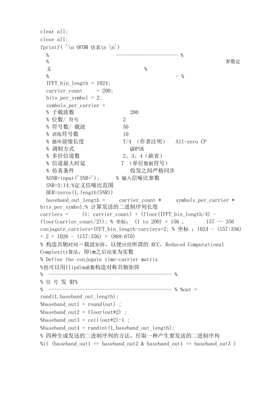
1、clear all;close all;fprintf( n OFDM 仿真n n)% %参数定义% - %IFFT_bin_length = 1024;carrier_count= 200;bits_per_symbol = 2;symbols_per_carrier = 50;% 子载波数200% 位数/ 符号2% 符号数/ 载波50% 训练符号数10% 循环前缀长度T/4 (作者注明)All-zero CP% 调制方式QDPSK% 多径信道数2、3、4(缺省)% 信道最大时延7 (单位数据符号)% 仿真条件收发之间严格同步%SNR=input(SNR=);% 输入信噪比参数SNR=3:1
2、4;%定义信噪比范围BER=zeros(1,length(SNR);baseband_out_length =carrier_count *symbols_per_carrier *bits_per_symbol;% 计算发送的二进制序列长度carriers =(1: carrier_count) + (floor(IFFT_bin_length/4) -floor(carrier_count/2); % 坐标: (1 to 200) + 156 ,157 - 356conjugate_carriers=IFFT_bin_length-carriers+2; % 坐标 :1024 - (157
3、:356) + 2 = 1026 - (157:356) = (869:670)% 构造共轭时间载波矩阵,以便应用所谓的 RCC,Reduced ComputationalComplexity算法,即ifft之后结果为实数% Define the conjugate time-carrier matrix%也可以用flipdim函数构造对称共轭矩阵% % 信 号 发 射% % %out = rand(1,baseband_out_length);%baseband_out1 = round(out) ;%baseband_out2 = floor(out*2) ;%baseband_out3
4、= ceil(out*2)-1 ;%baseband_out4 = randint(1,baseband_out_length);% 四种生成发送的二进制序列的方法,任取一种产生要发送的二进制序列%if (baseband_out1 = baseband_out2 & baseband_out1 = baseband_out3 )%fprintf(Transmission SequenceGenerated n n);%baseband_out = baseband_out1 ;%else%fprintf(Check Code n n);%end% 验证四种生成发送的二进制序列的方法baseb
5、and_out=round( rand(1,baseband_out_length);convert_matrix = reshape(baseband_out,bits_per_symbol,length(baseband_out)/bits_per_sy mbol);for k = 1length(baseband_out)/bits_per_symbol),modulo_baseband(k) = 0;for i = 1:bits_per_symbolmodulo_baseband(k) = modulo_baseband(k) + convert_matrix(i,k)*2(bits_
6、per_symbol - i);endend% 每2个比特转化为整数 0至3%采用lef t-msb方式%Test by lavabin%Abuilt-infunctionofdirectlychangebinarybitsintodecimalnumbers%convert_matrix1=zeros(length(baseband_out)/bits_per_symbol,bits_per_symbol);%convert_matrix1 = convert_matrix ;%Test_convert_matrix1=bi2de(convert_matrix1,bits_per_symbo
7、l,left-msb);%Test_convert_matrix2=bi2de(convert_matrix1,bits_per_symbol,right-msb);% 函数说明:% BI2DE Convert binary vectors to decimal numbers.% D = BI2DE(B) converts a binary vector B to a decimal value D. When B is% a matrix, the conversion is performed row-wise and the output D is a % column vector
8、of decimal values. The default orientation of thebinary % input is Right-MSB; the first element in B represents the least significant bit.%if (modulo_baseband = Test_convert_matrix1)% fprintf(modulo_baseband = Test_convert_matrix1 nnn);%else if (modulo_baseband = Test_convert_matrix2)%fprintf(modulo
9、_baseband = Test_convert_matrix2 nnn);%else%fprintf(modulo_baseband = any Test_convert_matrixnnn);%end%end% we get the result modulo_baseband = Test_convert_matrix1.% carrier_matrix reshape(modulo_baseband,carrier_count,symbols_per_carrier) % 生成时间载波矩阵% % QDPSK 调 制 % % carrier_matrix = zeros(1,carrie
10、r_count); carrier_matrix; % 添加一 个差分调制的初始相位,为0for i = 2symbols_per_carrier + 1)carrier_matrix(i, = rem(carrier_matrix(i, + carrier_matrix (i-1,2bits_per_symbol) ;% 差分调制endcarrier_matrix 二 carrier_matrix*(2*pi)/(2bits_per_symbol) ;% 产生差分相位X,Y=pol2cart(carrier_matrix,ones(size(carrier_matrix,1),size(ca
11、rrier_matrix,2); % 由极坐标向复 数坐标转化 第一参数为相位 第二参数为幅度% Carrier_matrix contains al l the phase informat ion and al l the ampl itudes are the plex_carrier_matrix = complex(X, Y) ;%添加训练序列training_symbols= 1j j 1-1 -j-j -1 1jj1-1-j-j-11jj1-1-j -j -11 j j1-1-j-j-11 j j1 -1 .-j -j -11 j j1-1-j-j-11 j j1 -1 -j-j
12、-11jj1-1-j-j-11j j 1 -1-j -j-1 1j j 1-1-j -j-1 .1 j j 1 -1-j-j-11 j j1 -1-j-j-1 1jj1-1-j-j-11jj1-1-j -j -1 1j j 1-1-j -j-1 1j j 1.-1 -j -j -1 1j j 1-1 -j-j -1 1j j 1 -1-j-j-11jj1-1-j-j-11 j j 1 -1-j-j-11 j j1 -1-j-j.-1 1 j j 1 -1 -j -j -1 1 j j 1 -1 -j -j -1 1 j j 1 -1 -j -j -1 1 j j 1-1 -j -j -1 ;
13、% 25 times 1 j j 1 , 25 times -1 -j -j -1, totally 200 symbols as a rowtraining_symbols = cat(1, training_symbols, training_symbols) ;training_symbols = cat(1, training_symbols, training_symbols) ;%Production of 4 rows of training_symbolscomplex_carrier_matrix=cat(1,training_symbols,complex_carrier_
14、matrix) ; % 训练序列与数据合并% block-type pilot symbolsIFFT_modulation = zeros(4 + symbols_per_carrier + 1,IFFT_bin_length)% Here a row vector of zeros is between training symbols and data symbols% 4 training symbols and 1 zero symbol% every OFDM symbol takes a row of IFFT_modulationIFFT_modulation(: , carr
15、iers) = complex_carrier_matrix; IFFT_modulation(: , conjugate_carriers) = conj(complex_carrier_matrix) % % Test by lavabin - Find the indices of zeros%index_of_zeros = zeros(symbols_per_carrier,IFFT_bin_length - 2*carrier_count);%IFFT_modulation1 = zeros(4 + symbols_per_carrier + 1,IFFT_bin_length);
16、 %IFFT_modulation2 = zeros(4 + symbols_per_carrier + 1,IFFT_bin_length); %IFFT_modulation1(6:symbols_per_carrier+5, = IFFT_modulation(6:symbols_per_carrier+5,=0 ;%for i = 1:symbols_per_carrier%index_of_zeros(i, = find(IFFT_modulation1(i+5,=1);%end% ti me_wave_ma trix = ifft(I FFT_modula ti on) ; % 进
17、行 IFFT 操作 time_wave_matrix=time_wave_matrix; %IfXisamatrix,ifftreturns the inverse Fourier transform of each column of the matrix.for i = 1: 4 + symbols_per_carrier + 1 windowed_time_wave_matrix(i,:)=real(time_wave_matrix(i,:);end% get the real part of the result of IFFT%这一步可以省略,因为IFFT结果都是实数%由此可以看出,
18、只是取了 IFFT之后载波上的点,并未进行CP的复制和添加 endofdm_modulation=reshape(windowed_time_wave_matrix,1,IFFT_bin_length*(4 + symbols_per_carrier + 1) ) ;% P2S operation%Test by lavabin%Another way of matrix transition%ofdm_modulation_tmp = windowed_time_wave_matrix.; %ofdm_modulation_test = ofdm_modulation_tmp(;%if (o
19、fdm_modulation_test = ofdm_modulation)% fprintf(ofdm_modulation_test = ofdm_modulation nnn);%else%fprintf(ofdm_modulation_test = ofdm_modulation nnn); %end% We get the result ofdm_modulation_test = ofdm_modulation . %Tx_data=ofdm_modulation;% % 信 道 模 拟% % d1=4;a1=0.2;d2=5;a2=0.3;d3=6;a3=0.4;d4=7;a4=
20、0.5; % 信道模拟copy1 = zeros(size(Tx_data) ;for i = 1 + d1: length(Tx_data) copy1(i) = a1*Tx_data( i - d1) ;endcopy2 = zeros(size(Tx_data) ) ;for i = 1 + d2: length( Tx_data) copy2(i) = a2*Tx_data( i - d2) ;end copy3 = zeros(size(Tx_data) ) ;for i = 1 + d3: length(Tx_data) copy3(i) = a3*Tx_data ( i - d3
21、) ;end copy4 = zeros(size(Tx_data) ) ;for i = 1 + d4: length( Tx_data) copy4(i) = a4*Tx_data(i - d4) ;endTx_data = Tx_data + copy1 + copy2 + copy3 + copy4; % 4 multi-paths Tx_signal_power = var(Tx_data);for idx=1:length(SNR)%monte carlo 仿真模拟linear_SNR = 10, SNR(idx) /IO);noise_sigma = Tx_signal_powe
22、r / linear_SNR; noise_scale_factor = sqrt(noise_sigma) ;noise = randn(1, length(Tx_data) )*noise_scale_factor; Rx_Data = Tx_data + noise;% % 信 号 接 收 % %Rx_Data_matrix = reshape(Rx_Data, IFFT_bin_length, 4+ symbols_per_carrier + 1)Rx_spectrum = fft(Rx_Data_matrix) ;% Suppose precise synchronazition b
23、etween Tx and Rx Rx_carriers = Rx_spectrum( carriers, : );Rx_training_symbols = Rx_carriers( (1: 4) , : ) ;Rx_carriers = Rx_carriers(5: 55), : ) ; % % 信 道 估 计% %Rx_training_symbols = Rx_training_symbols./ training_symbols;Rx_t raining_symbols_deno = Rx_t raining_symbols2;Rx_training_symbols_deno=Rx_
24、training_symbols_deno(1,+Rx_training_symbols_deno(2,+Rx_training_s ymbols_deno(3,+Rx_training_symbols_deno(4, ;Rx_training_symbols_nume = Rx_training_symbols(1, :)+Rx_training_symbols(2, :)+ Rx_training_symbols(3, :)+Rx_training_symbols(4, : ) ;Rx_training_symbols_nume = conj(Rx_training_symbols_num
25、e) ;% 取4个向量的导频符号是为了进行平均优化%都是针对“行向量”即单个的OFDM符号进行操作%原理:寻求1/H,对FFT之后的数据进行频域补偿% 1/H = conj(H)/2 because2 = H * conj(H)Rx_training_symbols=Rx_training_symbols_nume./Rx_training_symbols_deno;Rx_training_symbols=Rx_training_symbols_nume./Rx_training_symbols_deno;Rx_training_symbols_2=cat(1,Rx_training_symb
26、ols,Rx_training_symbols) ;Rx_training_symbols_4=cat(1,Rx_training_symbols_2,Rx_training_symbols_2)7Rx_training_symbols_8=cat(1,Rx_training_symbols_4,Rx_training_symbols_4)7Rx_training_symbols_16=Rx_training_symbols_8) ;cat(1,Rx_training_symbols_8,Rx_training_symbols_32=Rx_training_symbols_16) ;cat(1
27、,Rx_training_symbols_16,Rx_training_symbols_48=Rx_training_symbols_16) ;cat(1,Rx_training_symbols_32,Rx_training_symbols_50=Rx_training_symbols_2) ;cat(1,Rx_training_symbols_48,Rx_training_symbols=cat(1,Rx_training_symbols_50,Rx_training_symbols) ;Rx_carriers = Rx_training_symbols.*Rx_carriers; % 进行
28、频域单抽头均衡%Test of Using Rx_phase = angle(Rx_carriers)*(180/pi) phase_negative = find(Rx_phase 0) ;rem%Rx_phase1 = Rx_phase;%Rx_phase2 = Rx_phase;%Rx_phase1(phase_negative) = rem(Rx_phase1(phase_negative) + 360, 360) ; %Rx_phase2(phase_negative) = Rx_phase2(phase_negative) + 360 ;%if Rx_phase2(phase_ne
29、gative) = Rx_phase1(phase_negative)% fprintf(n There is no need using rem in negative phase transition.n) %else% fprintf(n We need to use rem in negative phase transition.n)%end%Rx_phase(phase_negative) = rem(Rx_phase(phase_negative) + 360, 360) ; % 把负的相位转化为正的相位Rx_decoded_phase = diff(Rx_phase) ;% 这
30、也是为什么要在前面加上初始相位的原因% “Here a row vector of ze ros is between training symbols and data symbols”phase_negative = find(Rx_decoded_phase 0) ;Rx_decoded_phase(phase_negative)= rem(Rx_decoded_phase(phase_negative) + 360, 360) ; % 再次把负的相位转化为正的相位% % QDPSK 解 调 % % base_phase = 360 /2bits_per_symbol; delta_ph
31、ase = base_phase /2;Rx_decoded_symbols=zeros(size(Rx_decoded_phase,1),size(Rx_decoded_phase,2) ;for i = 1: (2bits_per_symbol - 1)center_phase = base_phase*i;plus_delta = center_phase + delta_phase; % Decision threshold 1 minus_delta = center_phase - delta_phase; % Decision threshold 2 decoded=find(R
32、x_decoded_phase minus_delta) ;Rx_decoded_symbols(decoded) = i;end% 仅仅对三个区域进行判决% 剩下的区域就是零相位的空间了% 这个区域在定义解调矩阵时已经定义为零Rx_serial_symbols = reshape(Rx_decoded_symbols,1,size(Rx_decoded_symbols, 1)*size(Rx_decoded_symbols,2) ;for i = bits_per_symbol: -1: 1if i = 1Rx_binary_matrix(i, : ) = rem(Rx_serial_sym
33、bols, 2) ;Rx_serial_symbols = floor(Rx_serial_symbols/2) ; elseRx_binary_matrix( i, : ) = Rx_serial_symbols;endend% Integer to binarybaseband_in = reshape(Rx_binary_matrix, 1,size(Rx_binary_matrix, 1)*size(Rx_binary_matrix, 2) ) ;% % 误 码 率 计 算 % %bit_errors(idx) = find(baseband_in = baseband_out) ;%
34、 find的结果其每个元素为满足逻辑条件的输入向量的标号,其向量长度也就 是收发不一样的bit的个数%bit_error_count(idx) = size(bit_errors, 2) ; %total_bits = size( baseband_out, 2) ;%bit_error_rate = bit_error_count/ total_bits; %fprintf ( %f n,bit_error_rate) ;number_err(idx),BER(idx) = biterr(baseband_out,baseband_in ) ;endsemilogy(SNR,BER,r*);
35、legend(OFDM BER-SNR); xlabel(SNR (dB); ylabel(BER); title(OFDM);grid on;% % The END % % %1.该程序进行了简单的LMS信道估计,没有加入与MMSE等其他信道估计算法 的比较;%2.仿真条件为系统处于理想同步情况下。QjFile Edit View Insert Tools Desktop Window. Helpigure Zooiri lr: IOFDMTr10101010106SNR(dB)LU10 1 :-;= = = = = =匕=匕=;* OFDM BER-SNR10Matlab论坛iLoveMatlab,cn
- 温馨提示:
1: 本站所有资源如无特殊说明,都需要本地电脑安装OFFICE2007和PDF阅读器。图纸软件为CAD,CAXA,PROE,UG,SolidWorks等.压缩文件请下载最新的WinRAR软件解压。
2: 本站的文档不包含任何第三方提供的附件图纸等,如果需要附件,请联系上传者。文件的所有权益归上传用户所有。
3.本站RAR压缩包中若带图纸,网页内容里面会有图纸预览,若没有图纸预览就没有图纸。
4. 未经权益所有人同意不得将文件中的内容挪作商业或盈利用途。
5. 装配图网仅提供信息存储空间,仅对用户上传内容的表现方式做保护处理,对用户上传分享的文档内容本身不做任何修改或编辑,并不能对任何下载内容负责。
6. 下载文件中如有侵权或不适当内容,请与我们联系,我们立即纠正。
7. 本站不保证下载资源的准确性、安全性和完整性, 同时也不承担用户因使用这些下载资源对自己和他人造成任何形式的伤害或损失。
