 温度变送器外文翻译(中英文翻译)

《温度变送器外文翻译(中英文翻译)》由会员分享,可在线阅读,更多相关《温度变送器外文翻译(中英文翻译)(15页珍藏版)》请在装配图网上搜索。
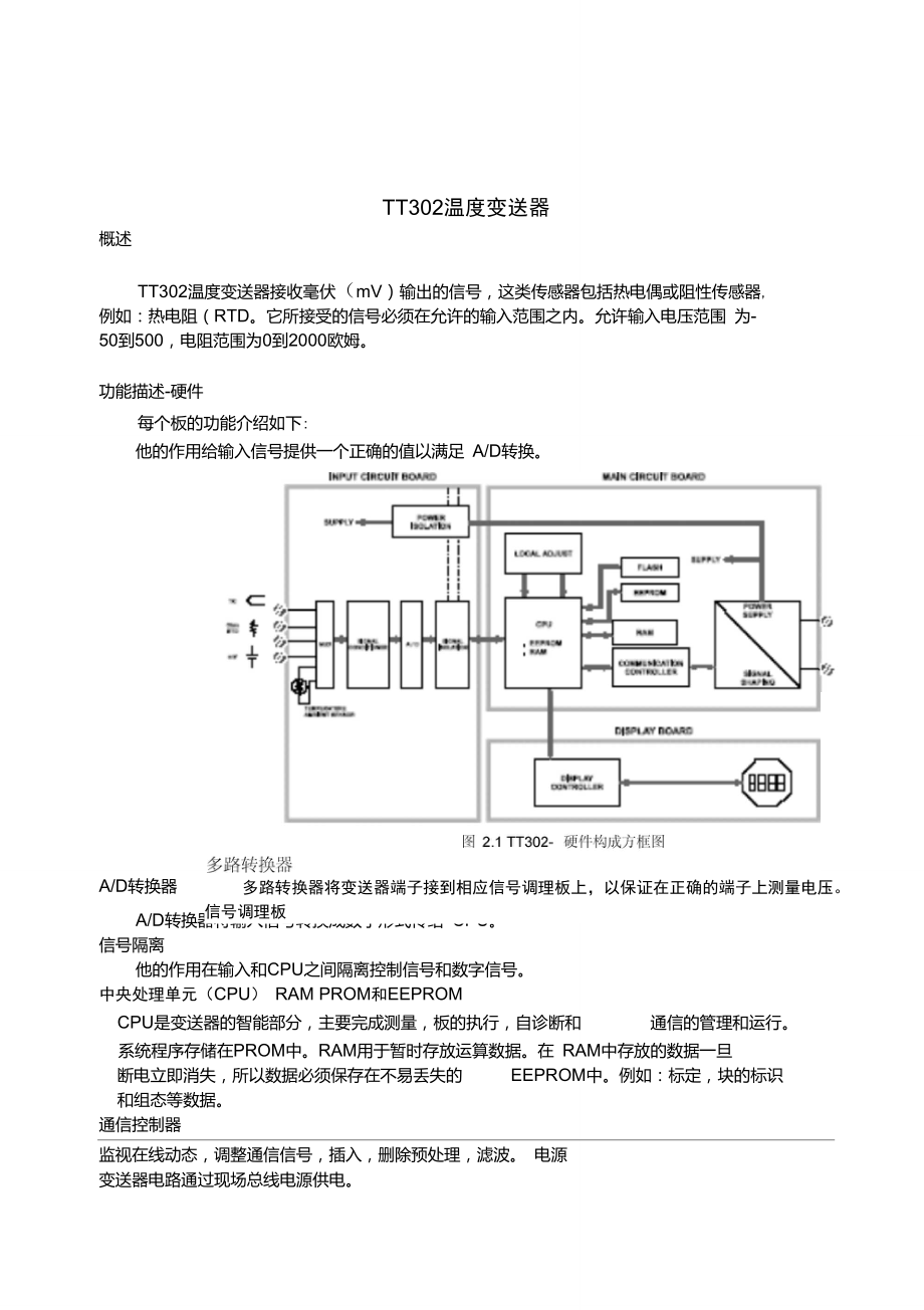
1、#TT302温度变送器概述TT302温度变送器接收毫伏(mV)输出的信号,这类传感器包括热电偶或阻性传感器, 例如:热电阻(RTD。它所接受的信号必须在允许的输入范围之内。允许输入电压范围 为-50到500,电阻范围为0到2000欧姆。功能描述-硬件每个板的功能介绍如下:多路转换器将变送器端子接到相应信号调理板上,以保证在正确的端子上测量电压。 信号调理板他的作用给输入信号提供一个正确的值以满足 A/D转换。A/D转换器A/D转换器将输入信号转换成数字形式传给 CPU。信号隔离他的作用在输入和CPU之间隔离控制信号和数字信号。中央处理单元(CPU) RAM PROM和EEPROMCPU是变送器
2、的智能部分,主要完成测量,板的执行,自诊断和通信的管理和运行。系统程序存储在PROM中。RAM用于暂时存放运算数据。在 RAM中存放的数据一旦 断电立即消失,所以数据必须保存在不易丢失的EEPROM中。例如:标定,块的标识和组态等数据。通信控制器监视在线动态,调整通信信号,插入,删除预处理,滤波。 电源变送器电路通过现场总线电源供电。电源隔离像信号隔离一样,供给输入部分的信号必须要隔离,电源隔离采用变压器将直流供电电源 转换成高频交流供电。显示控制器从CPU接收数据送给LCD显示器的显示部分,此时显示器必须处于打开状态。 本机调整它有两个磁性驱动开关,它们必须由磁性工具来驱动而不是机械或电的接
3、触。图2.2-LCD指示器温度传感器TT302像前面所描述的那样,可以兼容多种类型的传感器。TT302为使用热电偶或热电阻RTD测量温度进行了特殊设计。此类传感器的基本内容如下所述:热电偶热电偶由两种不同的金属或合金在一端连接在一起所组成的,被称为测量端或热端。 测量端必须放在测量点上,热电偶的另一端是打开的连接在温度变送器上,这一端称做参 考端或冷端。在大多数应用中,塞贝克效应可以充分解释热电偶的工作原理。热电偶是如何工作的(塞贝克效应)当金属丝的两端有温差时,在金属丝的没一端都会产生一个小的电动势,这种现象就 叫做塞贝克效应。当两种不同金属丝连接在一起,而另一端开放时,两端之间的温差将会
4、产生一个电压输出。现在,有两个重要的问题需要注意:首先,热电偶所产生的电压与测 量端和冷端的温度成比例,因此,为了得到被测温度必须加上参考端的温度,被称做冷端 温度补偿。TT302可以自动进行补偿。为此,在 TT302传感器端子装有一个温度传感器。 其次,如果热电偶与变送器端子之间的导线没有采用与热电偶相同的导线(例如:由热电 偶传感器或接线盒到变送器端子之间采用铜线)那么就会对温度测量产生影响,因此必须 要进行冷端补偿。热电偶的电势在冷端温度为 0C时与热端温度的关系用热电偶分度表来表示。分度表存储 在TT302的存储器中,他们是国际标准 NBS(B,E,J,K,N,R,S,T)和德国工业标
5、准DIN(L,U) 热电阻(RTD热电阻通常被称做 RTD,它的工作原理是金属的阻抗会随着温度的升高而增加,存储在TT302的中的热电阻分度表有日本工业标准 JIS1604-81 (Pt50,Pt100)。国际电工委员会 IEC,DIN,JIS1604-89 (Pt50,Pt100&Pt500),通用电气公司 GE(Cu10)和 DIN(Ni120)。为使热电阻能够正确测量温度,必须消除传感器到测量电路之间线路电阻所造成的影 响。在一些工业应用中,这些导线有几百米长,在环境温度变化剧烈的场所,消除线路电 阻的影响是极为重要的。TT302允许二线制连接,但可能会引起测量误差。此误差取决于接线的长
6、度和导线经 过处的温度(图2.3二线制连接在二线制连接中,电压U2与热电阻的阻值Rtd和导线的电阻R成正比U2=( Rtd+2RIRTD为了避免导线电阻的影响,推荐用三线制连接(图2.4三线制连接)或四线制连接(图 2.5三线制连接在三线制连接中,端子3是高阻抗输入端,因此,没有电流流过该导线,此导线上也 没有压降。电压U2-U1与电阻无关,因为导线电阻上的电压被抵消掉了,它仅与Rtd的电阻有关。U2-U 仁(RTD+R)x|-Rxl = R TDxIRTD图2.4三线制连接U2在四线制连接中,端子2和端子3是高阻抗输入端,因此,没有电流流过此端,也没 有压降产生。另外两根导线的电阻可不予考虑
7、,这两根导线上也没有测量点,因此电压 只与RTD电阻值有关4#双通道连接和二线制连接相似,也存在相同的问题(图2.6双通道连接)导线的电阻需要测量,而且在同一温度下测量也不能忽略他们的阻值,因为长度也会影响 使它们不同。RRRTOt图2.6双通道连接西门子SIMATIC PCS 7 PS 展望投资成本低标准化的系统基于标准化的部件,因此有高度的挠性和可变性。由于标准化技术的使用使 其具有开放性运行和维护成本低全自动化具有电厂设备所需的控制系统的特殊功能和部件顾客利益与设备的适应性强可根据电厂的规模和特性进行扩展和改变可改变它的性能和记忆功能由一个服务器来实现从单一控制到分散控制具备电厂所需的特
8、殊运行,监视,诊断和过程接口回顾 自1997年投入市场截止到2002年8月100%的销售率 在30多个国家投入使用控制领域:工业发电厂生物发电厂电厂单元机组的辅机成功的原因全自动化功率方案库的使用将SIMATIC PCS 7的兼容性增强创新性应用国际公认标准为控制和 HMI提供一种开放系统服务范围无论何时何地都可得到全球范围内的服务经验在工程和节约时间方面提供高质量的规划,管理和方案技术认证过热器与再热器过热器是一种将热量传给饱和蒸汽以提高其温度的换热器。蒸汽过热是中心电站所 采用的设计特点之一,过热增加了整体循环效率。另外,它降低了汽轮机末级叶片的湿度, 因此提高了汽机的内在效率。一般而言,
9、过热器可分为辐射式过热器、对流式过热器或联合式过热器,这取决于 热量是怎样从烟气传给蒸汽的。这些过热器具有不同的运行特性,在机组负荷的宽范围内 如能保持出口汽温不变,这样的特性是最希望的。当出口汽温变得过高,则会引起过热器 因部分过热而失效。对流过热器位于炉膛出口,或能够从燃烧的高温产物吸收热能的区域。对流过热器常 常通过一束水冷管来遮蔽炉膛辐射热。当这些管子留有足够的间隔时,也能遮断渣粒而减 少过热器上的结渣问题。在大型蒸汽发生器系统中,对流过热器常常分为两部分:一级过 热器和二级过热器。饱和蒸汽首先进入一级过热器而接受初始过热,一级过热器为于相对 低的烟温区,在部分过热后,蒸汽进到二级过热
10、器而完成其过热过程。使过热器分为两级 的主要原因是为蒸汽再热器提供一个空间,使烟气向蒸汽有效传热。辐射过热器没有对流过热器那样得到普遍使用。当需要辐射过热器时,它通常位于炉 膛壁上代替一端水冷管。另一种布置是使辐射过热器刚好在屏式管后面,辐射过热器是二 级过热器的中间部分。中心电站锅炉提供蒸汽再热。再热器一般是对流式,且通常位于一级与二级过热器之 间的空间。当蒸汽温度在汽机中部分膨胀后,它返回锅炉再热。离开再热器的蒸汽温度通 常等于过热蒸汽温度。因为再热器的设计在运行本质上与过热器一样,过热器的讨论将同 样适用于再热器。在过热器的热力设计中,首先确定蒸汽温度。一般而言这点在电站系统设计中完成,
11、 以平衡电站初始费用和服役期运行费用。近年来,对于所有蒸汽发生器系统,最佳蒸汽温 度约538C。热力设计中的第二步是近似确定所要求的过热器面积数量。在过热器表面积被确定后,下一步要考虑的是选择管子的长度、 管径和管子数。显然, 选择是一个反复的过程,先产生一个尝试解,查看其各种约束是否满足,从各种可接受解 中找到最优解。最佳过热器应该有给予设计汽温所必需的足够的传热表面。管子参数(长 度和直径)使得蒸汽压降和管子金属温度将不超过设计值。管子金属温度是一个重要参数, 对管子材料的选择有很大影响。另外,最佳过热器要使管子布置得使所产生的灰和渣最少。现代过热器有许多管子通道,管子都顺排布置而不用错排
12、布置。管子通常是圆管,外 径为5或6.3cm。没有附在管子上的扩展表面(如肋片),材料的选择取决于蒸汽温度和 压力。碳钢的允许温度达430C,常常用于低温过热器。铬-钼钢、不锈钢或某种类似的耐 热合金能承受高达650C的温度,因而它们被选做高温区过热器。温度调节与控制对过热器与再热器都很重要,蒸汽温度调节常常要在锅炉指定的时间 内进行,原则方法是增加或减少传热面积。蒸汽温度也可以通过调节热烟气温度和质量流 量来实现。一般而言,这些都是通过改变过量空气或者蒸发段效果来完成。在锅炉运行中,有许多因素影响离开过热器和再热器的蒸汽温度,它们包括锅炉负荷、过量空气、给水温度和受热面的清洁度。运行中蒸汽温
13、度的控制必须在不改变设备布置的 情况下完成,最有效的措施包括:烟气旁路,燃烧器控制,温度调节,烟气再循环,过量 空气以及分隔炉膛。烟气旁路是控制烟气流过过热器的流量,这种方法是主要缺点是高温区可动闸板操作 运行困难,且对负荷变化响应慢。燃烧器控制通常是控制火焰位置和燃烧速度,使燃烧器倾斜可以使火焰指向或离开过 热器,这将改变炉膛的吸热和过热器的烟气温度。随着锅炉负荷减小,燃烧器将逐一推出 运行,这将改变燃烧速度,从而改变流经过热器的烟气流量。温度调节是常使用的方法之一,温度调节器通常位于一级和二级过热器之间。有两种 基本形式的温度调节器:一种是管式,一部分过热蒸汽通过换热器管道,将热量传给锅炉
14、 水(可以是锅炉给水或锅炉汽包水),随后进入温度调节,从一级过热器分开的蒸汽将会 合,一起进入二级过热器;第二种温度调节器是将给水喷入过热蒸汽流中。给水蒸发使蒸 汽温度降低,控制给水量就可以控制蒸汽温度。必须注意要使喷水足够纯净,喷水要和过 热蒸汽很好地混合,从而使得第二级过热器的入口没有水滴。烟气再循环通常采用改变炉膛和过热器的吸收率来控制蒸汽温度,当需要蒸汽温度声 高时,从省煤器出口取出的一部分烟气将循环返回炉膛底部。因此,炉膛温度降低,导致 炉膛吸热减少,而炉膛出口烟温升高。这么高的烟温,加上烟气流量增加,将增加过热器 的传热速率,使蒸汽出口温度升高。温度控制也受所使用的过量空气量的影响
15、,过量空气越多,蒸汽出口温度将越高,其 原因与烟气再循环方法的原因类似。必须指出,太多的过量空气将导致锅炉燃烧效率降低。 分隔炉膛锅炉是将饱和蒸汽的生产安排在一段,而将过热蒸汽的生产安排在另一段。过热 汽温是通过控制两个炉膛中的燃烧速率来调节的,这一方法不经济,很少应用中心电站锅 炉。7译文:TT302 Field bus Temperature Tran smitterOperationThe TT302 accepts sig nals from mV gen erators such as thermocouples or resistive sen sors such asRTDs.
16、The criterio n is that the sig nal is within the range of the in put. For mV, the range is -50 to 500mV and for resista nee, 0-2000 Ohm.Functional Description - HardwareThe fun cti on of each block is described below.MUX MultiplexerThe MUX multiplexes the sen sor termi nals to the sig nal con diti o
17、ning sect ion en suri ng that the voltages are measured betwee n the correct term in als.Signal ConditionerIts fun cti on is to apply the correct gai n to the in put sig nals to make them suit the A/D -con verter. A/D ConverterThe A/D converts the in put sig nal to a digital format for the CPU.Signa
18、l IsolationIts fun cti on is to isolate the con trol and data sig nal betwee n the in put and the CPU.(CPU) Central Processing Unit, RAM, PROM and EEPROMThe CPU is the intelligent portion of the transmitter, being responsible for the management and operati on of measureme nt, block executi on, self-
19、diag no stics and com muni cati on. The program is stored in a PROM. For temporary storage of data there is a RAM. The data in the RAM is lost if the power is switched off. However there is a nonvolatile EEPROM where data that must be retained is stored. Examples, of such data are trim, calibration,
20、 block configuration and identification data.TT302 - Fieldbus Temperature TransmitterCommunication ControllerIt mon itors line activity, modulates and demodulates com muni cati on sig nals and in serts and deletes start and end delimiters.Power SupplyTakes power of the loop-l ine to power the tran s
21、mitter circuitry.Power IsolationJust like the sig nals to and from the in put sect ion, the power to the in put secti on must be isolated. Isolation is achieved by converting the DC supply into a high frequency AC supply and galva ni cally separati ng it using a tran sformer.Display ControllerReceiv
22、es data from the CPU informing which segments of the Liquid Crystal Display, should be turned on.Local AdjustmentThere are two switches that are magn etically activated. They can be activated by the magn etic tool without mecha ni cal or electrical con tact.Figure 2.2 - LCD In dicatorTemperature Sen
23、sorsThe TT302, as previously explained, accepts several types of sensors. The TT302 is specially desig ned for temperature measureme nt using thermocouples or Resistive Temperature Detectors (RTDs).Some basic con cepts about these sen sors are prese nted below.ThermocouplesThermocouples are con stru
24、cted with two wires made from differe nt metals or alloys joined at one end, called measuring junction or hot junction. The measuring junction should be placed at the point of measurement.The other end of the thermocouple is open and connected to the temperature transmitter. This point is called ref
25、erence junction or cold junction.For most applications, the Seebeck effect is sufficient to explain thermocouple behavior as followi ng:How the Thermocouple Works (Seebeck Effect)When there is a temperature difference along a metal wire, a small electric potential, unique to every alloy, will occur.
26、 This phenomenon is called Seebeck effect. When two wires of dissimilar metals are joined at one end, and left ope n at the other, a temperature differe nce betwee n the two ends will result in a voltage since the pote ntials gen erated by the dissimilar materials are differe nt and do not can cel e
27、ach other out. Now, two importa nt things must be no ted. First: the voltage gen erated by the thermocouple is proporti onal to the differe nce betwee n the measuring-junction and the cold junction temperatures. Therefore the temperature at the refere nce jun ctio n must be added to the temperature
28、derived from the thermocouple output, in order to find the temperature measured. This is called cold junction compensation, and is done automatically by the TT302, which has a temperature sen sor at the sen sor term in als for this purpose. Secon dly, if the thermocouple wires are not used, all the
29、way to the term in als of the transmitter (e.g., copper wire is used from sensor-head or marshaling box) will form new junctions with additi onal Seebeck effects. It will be created and ruin the measureme nt in most cases, since the cold-ju ncti on compe nsatio n will be done at the wrong point.NOTE
30、The relati on betwee n the measuri ng jun ctio n temperature and the gen erated mili-voltage is tabulated in thermocouple calibrati on tables for sta ndardized thermocouple types, the refere nce temperature being 0 oC.Stan dardized thermocouples that are commercially used, whose tables are stored in
31、 the memory of the TT302, are the followi ng:.NBS (B, E, J, K, N, R, S & T).DIN (L & U)Resistive Temperature Detectors (RTDs)Resistance Temperature Detectors, most commonly known as RTD s, are based on the principthat the resista nceof metal in creasesas its temperature in creases. Sta ndardized RTD
32、s, whose tables are stored in the memory of the TT302, are the follow ing:.JIS 1604-81 (Pt50 & Pt100).IEC, DIN, JIS 1604-89 (Pt50, Pt100 & Pt500).GE (Cu10) .DIN (Ni120) For correct measureme nt of RTD temperature, it is n ecessaryto elim in ate the effect of the resista nce of the wires conn ect ing
33、 the sen sor to the measuri ng circuit. In some in dustrial applications, these wires may be hundreds of meters long. This is particularly important at locati ons where the ambie nt temperature cha nges con sta ntly.The TT302 permits a 2-wire connection that may cause measuring errors, depending on
34、the len gth of connection wires and on the temperature to which they are exposed. (See Figure 2.3 -Two-Wire Conn ecti on).In a 2-wire connection, the voltage V2 is proportional to the RTD resistance plus the resistance of the wires.V2 = RTD + 2 x R x IFigure 2.3 - Two-Wire ConnectionFU 口11#In order
35、to avoid the resistance effect of the connection wires, it is recommended to use a 3-wire conn ecti on (See Figure 2.4 -Three-Wire Connection) or a 4-wire conn ecti on (See Figure 2.5 - Four - Wire Connection).In a 3-wire conn ecti on, termi nal 3 is a high impeda nce in put. Thus, no curre nt flows
36、 through that wire and no voltage drop is caused. The voltage V2-V1 is in depe ndent of the wire resista nces since they will be can celled, and is directly proporti onal to the RTD resista nce alone.V2-V1 =RTD + R x I - R x I = R TD x IFigure 2.4 - Three -Wire ConnectionRTDIn a 4-wire conn ecti on,
37、 termi nals 2 and 3 are high impeda nce in puts. Thus, no curre nt flows through those wires and no voltage drop is caused. The resistance of the other two wires is not of interest, since there is no measurementregistered on them. Hence the voltage V2 is directly proporti onal to the RTD resista nce
38、.#(V2 = RTD x I)RTDFigure 2.5 - Four - Wire Connection12#A differential or dual channel connection is similar to the two-wire connection and gives the same problem (See Figure 2.6 - Differential or Dual Connection). The resistanceof the wires will be measured and do not can cel each other out in a t
39、emperature measureme nt, since linearization will affect them differently.RFigure 2.6 - Differe ntial or Dual Conn ecti onflTCZRroiSIEMENSHighlight of SIMATIC PCS 7 PSLow inv estme nt costs. Modular system based on standard components, therefore high degree of flexibility and scalability.Open tha nk
40、s to the use of sta ndard tech no logies.Low operatio n and maintenance costs.Horiz on tai in tegrati on with Totally In tegrated Automati on.Control system specific functionality and components for power plant requirements.Customer Profits.Optimum adaptation to the requirements.Expansion and adapta
41、tions according to size and plant characteristic.Scalable performa nces and memories for con trol.Scalable from si ngle statio n to distributed con trol system with clie nt-server architecture.Power-pla nt-specificoperati onandmon itori ng,diag no sticsand processin terface.Facts & Figures of Simati
42、c PCS7 PSThe Scope.On the market since 1997.100 sold to date (as of 08/2002).In use in more tha n 30 coun tries.In con trol of:In dustrial power pla ntsBiomass power pla ntsAuxiliaries of power pla ntsReas ons behi nd this success.Totally In tegrated Au tomati on:Con siste nt use of SIMATIC PCS7 wit
43、h Power Solution Library.Inno vati on Nature:We provide an ope n system using intern ati onal recog ni zed sta ndards for con troland HMI.Compete nee:Worldwide services which are available for you any time, any where!.Experie nee:Project man ageme nt and process kno w-how guara ntee for high quality
44、 in project engin eeri ng and sav ing time.Superheater and ReheaterThe superheater is a heat exchanger in which heat is transferred to the saturated steam to in crease its temperature. Stream superheat ing is one of the desig n features accepted in central electric power stations. Superheating raise
45、 overall cycle efficiency. In addition, it reduces a moisture level in the last stages of the steam turb ine and thus in creases the turbi ne in ternal efficie ncy.Superheaters are commonly classified as either radiant superheaters, convectivesuperheaters, or combined superheaters,depending on how h
46、eat idtransferredfrom the gases to steam. These superheaters have different performaneecharacteristics. The feature that the outlet steam temperature can stay esse ntially con sta nt over a wide range of un it load is the most desirable. Whe n the outlet steam temperature becomes excessive, it may c
47、ause failures from overheati ng parts of the superheater.The conv ective superheater is located in the furn ace exit or in the zone where it can receive thermal en ergy from the high temperature produces of combusti on.The conv ective superheater is freque ntly scree ned from the furn ace radiati on
48、 by a bank of water-filled tubes. These tubes,when adequately spaced, can alsointerceptthe slag particle and reduce slagging problems in superheatrs.Convective superheaters in large steam generator systems are frequently split into two parts: the primary superheater and the sec on dary superheaater.
49、 Saturated steam firstenters the primary superheater and receives the initial heating. The primarysuperheater is located in a zone of relatively low gas temperature. After the partial heat ing steam moves to the sec on dary superheater and completes its superheaing process. The main reasons for spli
50、tting the superheater are to provide space for the steam reheater and to achieve an effective heat tran sfer from the gases the steam.The radiant superheater is not as commonly used as the convective superheater. Whe n the radia nt superheater is n eeded, it is usually placed on the furn ace wall re
51、placi ng a sect ion of water-filled tubes. Ano ther arran geme nt is to have the radiant superheater just behind the screen tubes. The radiant superheater is an in tegral part of the sec on dary superheater.Centralstationboilers provide for steam reheating. The reheater isessentially a convective ty
52、pe and usually located in the space between thee primary and sec on dary superheaters. After steam partially expa nds in the tub ine, it retur ns to the boiler for reheati ng. The temperature of steam leav ing the reheater is usually equal to the superheated steam temperature. Since the design and o
53、peration of reheater are essentiallythe same as superheaters, the discussionofsuperheaters will be equally applicable to reheaters.In superheater thermal desig n, the steam temperature is firstdeterm in ed. Thisis gen erally accomplished in the pla nt system desig n, bala ncing the pla nt in itial c
54、ost against the lifttimeoperating cost. In recent years the optimum steamtemperature is approximately 538C for all large steam generation systems. In the sec ond step, the amount of superheater surface required is approximated.After the amount of superheater surface id determ in ed, the n ext con si
55、derati on is to select the tube length, tube diameter, and the number of tubes. Evidently, the selecti on is an iterative process, gen erat ing a trial soluti on and check ing to see whether all con stra ints are met. From several acceptable soluti ons, the optimum is found. The optimum superheater
56、should have eno ugh heat tra nsfer surface n ecessary to give the desig n steam temperature. The tube parameters(le ngth and diameter) are such that the steam pressure drop and tube metal temperature willnot exceed the design values. The tube metal temperature is an important parameter and has a str
57、o ng in flue nee on the tube material selecti on.In additi on,the optimumsuperheater should have its tubes so spaced that minimum ash and slag deposits will result.Moder n superheaters have many tube passes, and the tubes are arran ged in-li ne rather than staggered. The tubes are usually cylindrica
58、l and have 5 or 6.3cm outside diameter. There is no extended surface(i.e.fins)attachedto the tubes. Thematerial selectio n depe nds on the steam temperature and pressure. Carbon steel has an allowable temperature up to 430C and is frequently used for loe-temperature superheaters. Chrome-moly, sta in
59、 less steel, or same similar heat resista nt alloy can withstand the temperature up to 650 C . Therefore they are selected for the Superheater in a high-temperature zone.Temperature regulati on and con trol are importati on for both superheaters and reheaters. Steam temperature adjustme nts are freq
60、ue ntly made at the time of the commissioning of a boiler. The principal methods are an addition or regulating the hot gas temperature and mass flow rate. These are gen erally accomplished by cha nging the excess air or the effective ness of the evaporati on secti on.During a boiler operati on, ther
61、e are many factors affecti ng the temperature of steam leaving the superheater and reheater. These include a boiler load, excess air, feedwater temperature, and cleanliness of heating surfaces. Control of steam temperature duri ng operatio n must be done without cha nging the arran geme nt of equipm
62、ent. The most effectiveapproaches are gas bypass, burner control,attemperation, gas recirculation, excess air, divided furnace.A gas bypass is to controlthe gas flow rate to superheater.The maindisadva ntages of this approach are the operati ng difficulties experie need by the movable dampers locate
63、d in the high-temperature zone and the slow response to load cha nge.Burner control is used to control the flame location and combustion rate.Tilti ng bur ners can direct the flame toward or away from the superheater. These will result in a cha nge of heat absorptio n in the fur nace and cha nge of
64、gas temperature in the superheater. As the boiler load is reduced, burners are removed one by one from service. This will cha nge the combusti on rate and, thus, cha nge the gas flow rate to the superheater.Attemperation is one of approaches frequently used. The attemperator is usually located at the point betwee n the primary and sec on dary superheaters.There are two basic types of attemperator. The first is the tubular type in which some of superheated steam is passed through the tub
- 温馨提示:
1: 本站所有资源如无特殊说明,都需要本地电脑安装OFFICE2007和PDF阅读器。图纸软件为CAD,CAXA,PROE,UG,SolidWorks等.压缩文件请下载最新的WinRAR软件解压。
2: 本站的文档不包含任何第三方提供的附件图纸等,如果需要附件,请联系上传者。文件的所有权益归上传用户所有。
3.本站RAR压缩包中若带图纸,网页内容里面会有图纸预览,若没有图纸预览就没有图纸。
4. 未经权益所有人同意不得将文件中的内容挪作商业或盈利用途。
5. 装配图网仅提供信息存储空间,仅对用户上传内容的表现方式做保护处理,对用户上传分享的文档内容本身不做任何修改或编辑,并不能对任何下载内容负责。
6. 下载文件中如有侵权或不适当内容,请与我们联系,我们立即纠正。
7. 本站不保证下载资源的准确性、安全性和完整性, 同时也不承担用户因使用这些下载资源对自己和他人造成任何形式的伤害或损失。
