 同步发电机pscad详细建模过程

《同步发电机pscad详细建模过程》由会员分享,可在线阅读,更多相关《同步发电机pscad详细建模过程(8页珍藏版)》请在装配图网上搜索。
1、Synchronous Machine Study - 1Methods of Initializing a Synchronous MachineMotivation:The objective of this application note is to familiarize the user with the synchronous machine model in PSCAD and demonstrate various methods of initializing the synchronous machine to reach a specific load flow ste
2、ady state condition.System Overview:In order to investigate the effect of various phenomena such as faults etc in the system; it is crucial that the system is initialized properly and is under proper steady state load flow conditions.In PSCAD the recommended method of initializing the machine is to
3、start it as a fixed voltage source and use this mode of operation to determine exciter and governor input (or field voltage and mechanical torque) parameters needed to produce the desired steady state load flow condition.Note: The synchronous machine model in PSCAD provides users with the option of
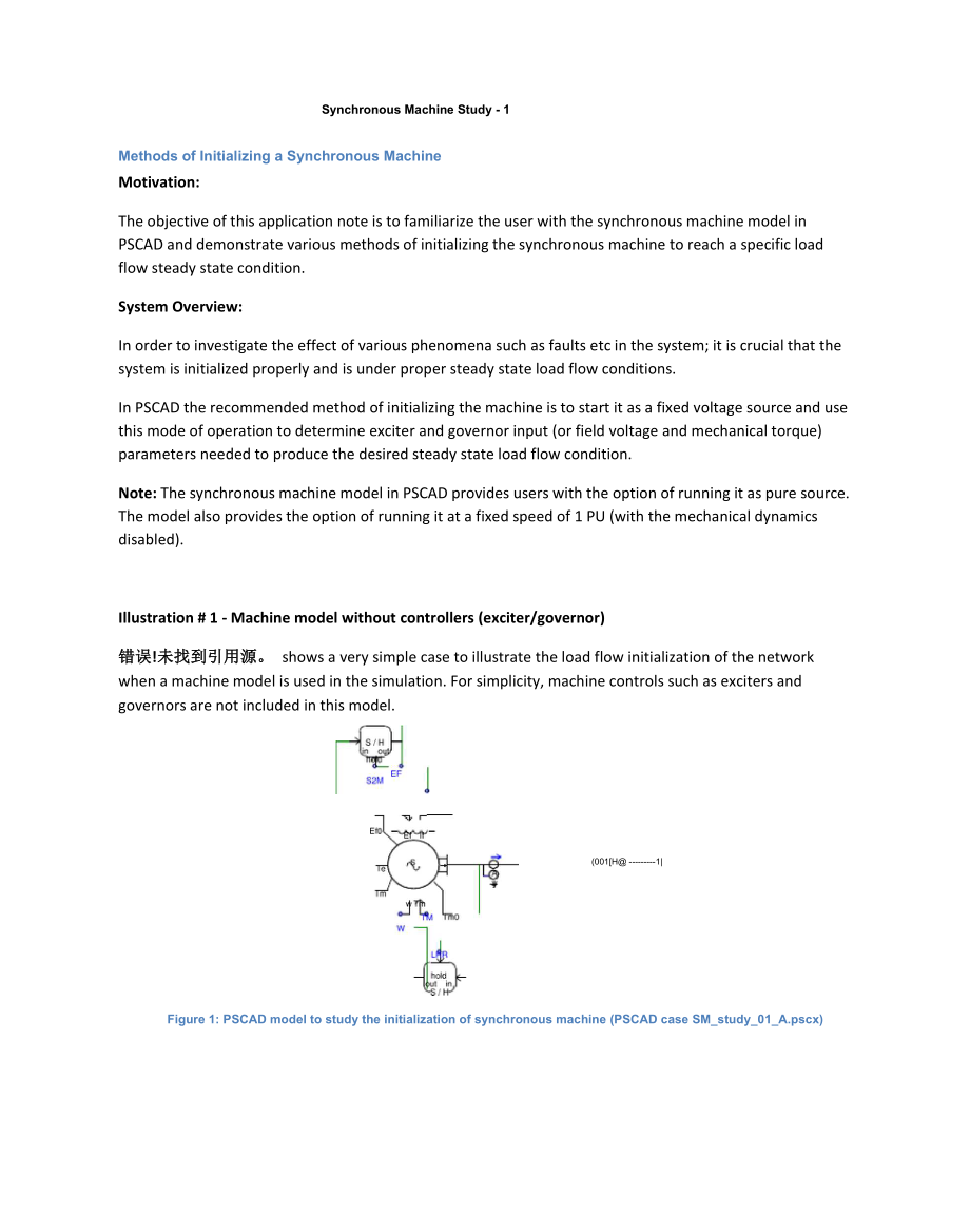
4、running it as pure source. The model also provides the option of running it at a fixed speed of 1 PU (with the mechanical dynamics disabled).Illustration # 1 - Machine model without controllers (exciter/governor)错误!未找到引用源。 shows a very simple case to illustrate the load flow initialization of the ne
5、twork when a machine model is used in the simulation. For simplicity, machine controls such as exciters and governors are not included in this model.(001H1|Figure 1: PSCAD model to study the initialization of synchronous machine (PSCAD case SM_study_01_A.pscx)At time t = 0, machine is run as a pure
6、source with its terminal voltage magnitude and phase specified by the user. To operate the machine as a pure source set the initial condition option in the parameter to none, as shown in Figure 2. By doing so the user can specify the terminal voltage conditions alone and properly initialize the mach
7、ine and the network to a specific load flow. Synchronous PAschineuSynchroixhji; MachineTwh i-eliLirfegfr For Smitia I eoniditio ra iype-ctioicer syrrtwlT 匚Tyg RetLrn vbIle-c曰 Ger*erlTerminal Vollao e Magnitude aLlnie= 0-Termlnjl VQltaa a Pha 艷 at Time = 0-l.C4p.u.|0.75 F制|Machine nameHydr&GerlffNo.
8、of Q-aw 9 Dam per Win dip a 3GueDjtn Entry Farmsst:GererelnrMultin* ass i nLerfaceEndb les 立i ee d CtrlDEABLEArmature Rreistflnoe 仍:RescranceD-aad-s 5?tur?tJ an口出#Type af scttlpgsfar initi al conditlari Noura to w.3chlneLj tnantlon52ML&ck-rntnrCll - Nc-rmal eudafljlrmalbanLHREndbl 3戊4曰已 F coicrolai1
9、 sauruD|Jirt4lTing 如 poyro.a 阳ErublgiSd已亡 lienldcoicrol0Inertii c-slmg FjrtDrL.Qbampr fricti-i FactorL.aF-sdtof for dftfipirtijL.aErdhl|lE|aiibJ P coitral 口f Lacked rutiir mhnHFi ld Vluaemuhipbei-L.OtfrTiuWpiiCfltHJn0GwnvralQk ICancel 1M*p- 1咱MKhrw:Simulation ResultsFigure 4 shows the variation of t
10、he machine parameters when it is switched from source to machine mode at t= 2sec and also when the rotor is released at t=2.5sec.0.05.010.015.020.025.0Figure 4: Simulation resultsm)MLRWarkHBn.xrV. 5wL ag-tarcsdrynme-eaSvaEueIllustration # 2- Machine model with exciter, governor and turbine models in
11、 the simulation.For a more realistic simulation, the exciters and governors and turbine models should be included in the simulation. Figure 5 shows the PSCAD model of synchronous machine with the exciter model in place.v = 17.95l|aTimer LRRS2M0.01 HAs explained in the previous case, set the initial
12、terminal voltage magnitude and phase of the synchronous machine and operate it as a pure source. The terminal voltage magnitude and phase, set with respect toa reference bus (equivalent voltage source) ensures the desired active and reactive power flow.The exciter is initialized at the time instant
13、when S2M changes state. This can be ensured by setting the output controller initialization variable (InitEx) (defined in the machine model) as shown in Figure 6. The same signal name is used inside the exciter model to define the instant that it should initialize its internal parameters and output
14、the desired field voltage (Ef) value as given by Ef0.u” Type AC EDeciter唱 Synchronous IVdnine|SSIB釘看才El GeneralAC Erater lyp 亡AC1AExciter Status: 0- nitial ze? I N orrrial Int&K Output internally CQmpLrtsd initsIVref? Vee Load CompenEatirg Reei9tarce (Rc0.0 p.u.Load Compenssting Reactance: (Xc)a. p.
15、u.Transducer Time Constiani: (TR)a. eedIs there a Stabilizer ?NoemeralattanFigure 6: Controller initialization variableCancelFigure 7 shows the control signals to the synchronous machine and the exciter.Figure 7: Control signals.Note that, in addition to the desired output field voltage to the machi
16、ne (Ef0), the field current (If) and the terminal voltage and current (VT/IT) are provided as inputs to the exciter model. PSCAD then calculates the initialized value of the reference voltage Vref0 need to maintain the steady state operating condition. Vref0 is the initialized voltage set point to m
17、aintain the specified steady state terminal conditions. Once the system enters steady state, a sample and hold component can be used to hold this steady state reference voltage and feed the signal back to the exciter through input Vref.Note 1: During initialization the machine is operated as pure so
18、urce.Note 2: If the user needs to change the voltage reference point during the simulation, this can be achieved through an external (variable) input which is given a zero value initially, Figure 8.Voltage referenceMain .T - Tme=Jd3m + B3dtm(1)Voltage refe.-loo=E釋00.5Figure 8: option for variable re
19、ference controlGovernor and turbine initializationAfter the initial transients have settled the machine mode was activated by switching S2M from 0 to 1. At this instant the rotor will be spinning at a constant speed as the machine is still in locked rotor state. The governors and turbines can be ini
20、tialized at the time instant when the rotor is unlocked i.e. when the signal LRR is switched to 1. Once this happens the mechanical dynamics, as defined by equation (1) is active.The simulation model with a governor/turbine model is shown in Figure 9. These models are initialized in a manner similar
21、 to that used to initialize the exciter. Signal InitGv (Figure 6) is the control signal used to activate the initialization of the governor1.0”诃叫卜0.1 HFigure 9: PSCAD model for synchronous machines with exciter, governor and turbines (PSCAD case SM_study_01_B.pscx)Simulation resultsThe variation of
22、the various machine parameters when it is switched from source to machine mode at 2sec and also when the rotor dynamics are activated at t=2.5sec in shown in Figure 10.Figure 10: Simulation results using governor and exciterAt the point in time when the machines are running free and the excitation and governor systems are stable, a snapshot can be taken. Faults and disturbances can be applied to the system with the start-up commencing from the snapshot file.PSCAD:Refer to PSCAD case: SM_study_01_A.pscx and SM_study_01_B.pscx
- 温馨提示:
1: 本站所有资源如无特殊说明,都需要本地电脑安装OFFICE2007和PDF阅读器。图纸软件为CAD,CAXA,PROE,UG,SolidWorks等.压缩文件请下载最新的WinRAR软件解压。
2: 本站的文档不包含任何第三方提供的附件图纸等,如果需要附件,请联系上传者。文件的所有权益归上传用户所有。
3.本站RAR压缩包中若带图纸,网页内容里面会有图纸预览,若没有图纸预览就没有图纸。
4. 未经权益所有人同意不得将文件中的内容挪作商业或盈利用途。
5. 装配图网仅提供信息存储空间,仅对用户上传内容的表现方式做保护处理,对用户上传分享的文档内容本身不做任何修改或编辑,并不能对任何下载内容负责。
6. 下载文件中如有侵权或不适当内容,请与我们联系,我们立即纠正。
7. 本站不保证下载资源的准确性、安全性和完整性, 同时也不承担用户因使用这些下载资源对自己和他人造成任何形式的伤害或损失。
