 离子推进器结构及应用

《离子推进器结构及应用》由会员分享,可在线阅读,更多相关《离子推进器结构及应用(17页珍藏版)》请在装配图网上搜索。
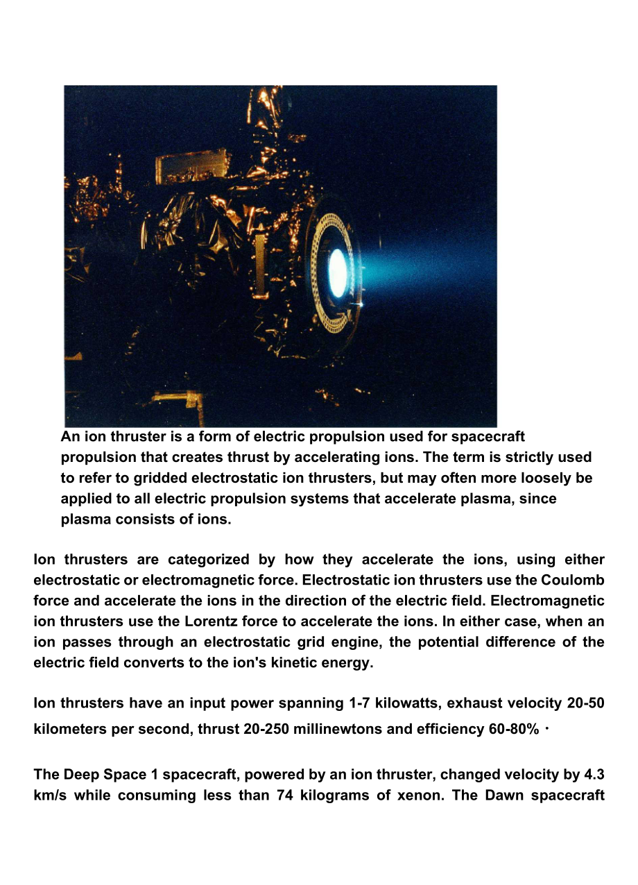
1、An ion thruster is a form of electric propulsion used for spacecraft propulsion that creates thrust by accelerating ions. The term is strictly used to refer to gridded electrostatic ion thrusters, but may often more loosely be applied to all electric propulsion systems that accelerate plasma, since
2、plasma consists of ions.Ion thrusters are categorized by how they accelerate the ions, using either electrostatic or electromagnetic force. Electrostatic ion thrusters use the Coulomb force and accelerate the ions in the direction of the electric field. Electromagnetic ion thrusters use the Lorentz
3、force to accelerate the ions. In either case, when an ion passes through an electrostatic grid engine, the potential difference of the electric field converts to the ions kinetic energy.Ion thrusters have an input power spanning 1-7 kilowatts, exhaust velocity 20-50 kilometers per second, thrust 20-
4、250 millinewtons and efficiency 60-80% The Deep Space 1 spacecraft, powered by an ion thruster, changed velocity by 4.3 km/s while consuming less than 74 kilograms of xenon. The Dawn spacecraft broke the record, reaching 10 km/s.Applications include control of the orientation and position of orbitin
5、g satellites (some satellites have dozens of low-power ion thrusters) and use as a main propulsion engine for low-mass robotic space vehicles (for example Deep Space 1 and Dawn).Ion thrusters are not the most promising type of electrically powered spacecraft propulsion (although in practice they hav
6、e been more successful than others).The ion drive is comparable to a car that takes two days to accelerate from zero to 60 miles per hour; a real ion engines technical characteristics, and especially its thrust, are considerably inferior to its literary prototypes.Technical capabilities of the ion e
7、ngine are limited by the space charge created by ions. This limits the thrust density (force per cross-sectional area of the engine). Ion thrusters create small thrust levels (for example the thrust of Deep Space 1s engine approximately equals the weight of one sheet of paper) compared to convention
8、al chemical rockets, but achieve very high specific impulse, or propellant mass efficiency, by accelerating their exhaust to high speed. However, ion thrusters carry a fundamental price: the power imparted to the exhaust increases with the square of its velocity while thrust increases linearly. Chem
9、ical rockets, on the other hand, can provide high thrust, but are limited in total impulse by the small amount of energy that can be stored chemically in the propellants.Given the practical weight of suitable power sources, the accelerations given by ion thrusters are frequently less than one thousa
10、ndth of standard gravity. However, since they operate as electric (or electrostatic) motors, a greater fraction of the input power is converted into kinetic exhaust power than in a chemical rocket. Chemical rockets operate as heat engines, hence Carnots theorem bounds their possible exhaust velocity
11、.Due to their relatively high power needs, given the specific power of power supplies and the requirement of an environment void of other ionized particles, ion thrust propulsion is currently only practical on spacecraft that have already reached space, and is unable to take vehicles from Earth to s
12、pace. Spacecraft rely on conventional chemical rockets to initially reach orbit.OriginsThe first person to publish mention of the idea was Konstantin Tsiolkovsky in 1911.However, the first documented instance where the possibility of electric propulsion was considered is found in Robert H. Goddards
13、handwritten notebook in an entry dated September 6, 1906.The first experiments with ion thrusters were carried out by Goddard at Clark University from 1916-917 The technique was recommended for near-vacuum conditions at high altitude, but thrust was demonstrated with ionized air streams at atmospher
14、ic pressure. The idea appeared again in Hermann Oberths Wege zur Raumschiffahrt” (W ays to Spaceflight), published in 1923, where he explained his thoughts on the mass savings of electric propulsion, predicted its use in spacecraft propulsion and attitude control, and advocated electrostatic acceler
15、ation of charged gases.A working ion thruster was built by Harold R. Kaufman in 1959 at the NASA Glenn Research Center facilities. It was similar to the general design of a gridded electrostatic ion thruster with mercury as its fuel. Suborbital tests of the engine followed during the 1960s and in 19
16、64 the engine was sent into a suborbital flight aboard the Space Electric Rocket Test 1 (SERT 1).It successfully operated for the planned 31 minutes before falling back to Earth. This test was followed by an orbital test, SERT-2, in 1970.An alternate form of electric propulsion, the Hall effect thru
17、ster was studied independently in the U.S. and the Soviet Union in the 1950s and 1960s. Hall effect thrusters had operated on Soviet satellites since 1972. Until the 1990s they were mainly used for satellite stabilization in North-South and in East-West directions. Some 100-200 engines completed the
18、ir mission on Soviet and Russian satellites until the late 1990s.Soviet thruster design was introduced to the West in 1992 after a team of electric propulsion specialists, under the support of the Ballistic Missile Defense Organization, visited Soviet laboratories.General descriptionIon thrusters us
19、e beams of ions (electrically charged atoms or molecules) to create thrust in accordance with momentum conservation. The method of accelerating the ions varies, but all designs take advantage of the charge/mass ratio of the ions. This ratio means that relatively small potential differences can creat
20、e very high exhaust velocities. This reduces the amount of reaction mass or fuel required, but increases the amount of specific power required compared to chemical rockets. Ion thrusters are therefore able to achieve extremely high specific impulses. The drawback of the low thrust is low spacecraft
21、acceleration, because the mass of current electric power units is directly correlated with the amount of power given. This low thrust makes ion thrusters unsuited for launching spacecraft into orbit, but they are ideal for in-space propulsion applications.Various ion thrusters have been designed and
22、 they all generally fit under two categories. The thrusters are categorized as either electrostatic orelectromagnetic. The main difference is how the ions are accelerated.Electrostatic ion thrusters use the Coulomb force and are categorized as accelerating the ions in the direction of the electric f
23、ield.Electromagnetic ion thrusters use the Lorentz force to accelerate the ions.Electric power supplies for ion thrusters are usually solar panels but, at sufficiently large distances from the Sun, nuclear power is used. In each case the power supply mass is essentially proportional to the peak powe
24、r that can be supplied, and they both essentially give, for this application, no limit to the energy.Electric thrusters tend to produce low thrust, which results in low acceleration. Using 1 g is 9.81 m/s2; F = m a a = F/m. An NSTAR thruster producing a thrust (force) of 92 mN will accelerate a sate
25、llite with a mass of 1,000 kg by 0.092 N / 1,000 kg = 0.000092 m/s2 (or 9.38x10⁻⁶ g)thrust = 2*n*power/(g * Isp)Wherethrust is the force in Nn is the efficiency, a dimensionless value between 0 and 1 (70% efficiency is 0.7)power is the electrical energy going into the thruster in Wg is a constant, t
26、he acceleration due to gravity 9.81 m/s2Isp is the Specific impulse in sElectrostatic ion thrustersANODEELECTRONION;jrOPI-i i ajt DISCHARGE atom PLASMAION BEAMELECTRONS IMPACTATOMS TO 匚REMEION5POSITIVE NEGATIVE GRIDGRID (+1090V)(-225VKELECTRONS EMITTED BY HOLLOW CATHODE TRAVERSE DISCHARGE AND ARE CO
27、LLECTED BY ANODEMAGNETIC FIELDENHANCES IONIZATIONEFFICIENCYIONS ELECTROSTATICALLY ACCELERATED-1 MAGNET” RINGSELECTRONS INJECTED INTO BEAM FOR NEUTRALIZATIONPROPELLANTINJECTIONHOLLOW CATHODE PLASMA BRIDGE NEUTRALIZERGridded electrostatic ion thrusters See also: electrostatic ion thrusterGridded elect
28、rostatic ion thrusters commonly utilize xenon gas. This gas has no charge and is ionized by bombarding it with energetic electrons. These electrons can be provided from a hot cathode filament and when accelerated in the electrical field of the cathode, fall to the anode. Alternatively, the electrons
29、 can be accelerated by the oscillating electric field induced by an alternating magnetic field of a coil, which results in a self-sustaining discharge and omits any cathode (radio frequency ion thruster).The positively charged ions are extracted by an extraction system consisting of 2 or 3 multi-ape
30、rture grids. After entering the grid system via the plasma sheath the ions are accelerated due to the potential difference between the first and second grid (named screen and accelerator grid) to the final ion energy of typically 1keV, thereby generating the thrust.Ion thrusters emit a beam of posit
31、ive charged xenon ions only. To avoid charging up the spacecraft, another cathode is placed near the engine, which emits electrons (basically the electron current is the same as the ion current) into the ion beam. This also prevents the beam of ions from returning to the spacecraftand cancelling the
32、 thrust.Gridded electrostatic ion thruster research (past/present):NASA Solar Technology Application Readiness (NSTAR) - 2.3 kW, used on two successful missionsNASAs Evolutionary Xenon Thruster (NEXT) - 6.9 kW, flight qualification hardware builtNuclear Electric Xenon Ion System (NEXIS)High Power El
33、ectric Propulsion (HiPEP) - 25 kW, test example built and run briefly on the groundEADS Radio-Frequency Ion Thruster (RIT)Dual-Stage 4-Grid (DS4G)Hall effect thrustersSee also: Hall effect thrusteranode /gas distributorin nermag neticmagnetic outer magnetic circuitthruster exhaustHall effect thruste
34、rs accelerate ions with the use of an electric potential maintained between a cylindrical anode and a negatively charged plasma that forms the cathode. The bulk of the propellant (typically xenon gas) is introduced near the anode, where it becomes ionized, and the ions are attracted towards the cath
35、ode; they accelerate towards and through it, picking up electrons as they leave to neutralize the beam and leave the thruster at high velocity.The anode is at one end of a cylindrical tube, and in the center is a spike that is wound to produce a radial magnetic field between it and the surrounding t
36、ube. The ions are largely unaffected by the magnetic field, since they are too massive. However, the electrons produced near the end of the spike to create the cathode are far more affected and are trapped by the magnetic field, and held in place by their attraction to the anode. Some of the electro
37、ns spiral down towards the anode, circulating around the spike in a Hall current. When they reach the anode they impact the uncharged propellant and cause it to be ionized, before finally reaching the anode and closing the circuit.Field-emission electric propulsionField-emission electric propulsion
38、(FEEP) thrusters use a very simple system of accelerating ions to create thrust. Most designs use either caesium or indium as the propellant. The design comprises a small propellant reservoir that stores the liquid metal, a narrow tube or a system of parallel plates that the liquid flows through, an
39、d an accelerator (a ring or an elongated aperture in a metallic plate) about a millimeter past the tube end. Caesium and indium are used due to their high atomic weights, low ionization potentials, and low melting points. Once the liquid metal reaches the end of the tube, an electric field applied b
40、etween the emitter and the accelerator causes the liquid surface to deform into a series of protruding cusps (Taylor cones). At a sufficiently high applied voltage, positive ions are extracted from the tips of the cones.The electric field created by the emitter and the accelerator then accelerates t
41、he ions. An external source of electrons neutralizes the positively charged ion stream to prevent charging of the spacecraft.Electromagnetic thrustersPulsed inductive thrustersPulsed inductive thrusters (PIT) use pulses of thrust instead of one continuousthrust, and have the ability to run on power
42、levels in the order of Megawatts (MW). PITs consist of a large coil encircling a cone shaped tube that emits the propellant gas. Ammonia is the gas commonly used in PIT engines. For each pulse of thrust the PIT gives, a large charge first builds up in a group of capacitors behind the coil and is the
43、n released. This creates a current that moves circularly in the direction of jO. The current then creates a magnetic field in the outward radial direction (Br), which then creates a current in the ammonia gas that has just been released in the opposite direction of the original current. This opposit
44、e current ionizes the ammonia and these positively charged ions are accelerated away from the PIT engine due to the electric field jO crossing with the magnetic field Br, which is due to the Lorentz Force.Magnetoplasmadynamic (MPD) / lithium Lorentz force accelerator (LiLFA)Magnetoplasmadynamic (MPD
45、) thrusters and lithium Lorentz force accelerator (LiLFA) thrusters use roughly the same idea with the LiLFA thruster building off of the MPD thruster. Hydrogen, argon, ammonia, and nitrogen gas can be used as propellant. In a certain configuration, the ambient gas in Low Earth Orbit (LEO) can be us
46、ed as a propellant. The gas first enters the main chamber where it is ionized into plasma by the electric field between the anode and the cathode. This plasma then conducts electricity between the anode and the cathode. This new current creates a magnetic field around the cathode, which crosses with
47、 the electric field, thereby accelerating the plasma due to the Lorentz force. The LiLFA thruster uses the same general idea as the MPD thruster, except for two main differences. The first difference is that the LiLFA uses lithium vapor, which has the advantage of being able to be stored as a solid.
48、 The other difference is that the cathode is replaced by multiple smaller cathode rods packed into a hollow cathode tube. The cathode in the MPD thruster is easily corroded due to constant contact with the plasma. In the LiLFA thruster the lithium vapor is injected into the hollow cathode and is not
49、 ionized to its plasma form/corrode the cathode rods until it exits the tube. The plasma is then accelerated using the same Lorentz Force.Electrodeless plasma thrustersElectrodeless plasma thrusters have two unique features: the removal of the anode and cathode electrodes and the ability to throttle
50、 the engine. The removal of the electrodes takes away the factor of erosion, which limits lifetime on other ion engines. Neutral gas is first ionized by electromagnetic waves and then transferred to another chamber where it is accelerated by an oscillating electricand magnetic field, also known as t
51、he ponderomotive force. This separation of the ionization and acceleration stage give the engine the ability to throttle the speed of propellant flow, which then changes the thrust magnitude and specific impulse values.Helicon double layer thrusterA helicon double layer thruster is a type of plasma
52、thruster, which ejects high velocity ionized gas to provide thrust to a spacecraft. In this thruster design, gas is injected into a tubular chamber (the source tube) with one open end. Radio frequency AC power (at 13.56 MHz in the prototype design) is coupled into a specially shaped antenna wrapped
53、around the chamber. The electromagnetic wave emitted by the antenna causes the gas to break down and form a plasma. The antenna then excites a helicon wave in the plasma, which further heats the plasma. The device has a roughly constant magnetic field in the source tube (supplied by solenoids in the
54、 prototype), but the magnetic field diverges and rapidly decreases in magnitude away from the source region, and might be thought of as a kind of magnetic nozzle. In operation, there is a sharp boundary between the high density plasma inside the source region, and the low density plasma in the exhau
55、st, which is associated with a sharp change in electrical potential. The plasma properties change rapidly across this boundary, which is known as a current-free electric double layer. The electrical potential is much higher inside the source region than in the exhaust, and this serves both to confin
56、e most of the electrons, and to accelerate the ions away from the source region. Enough electrons escape the source region to ensure that the plasma in the exhaust is neutral overall.ComparisonsThe following table compares actual test data of some ion thrusters:EnginePropellantRequired powerkW)Speci
57、fic LCflpulses)Thrust(nd)llirustermass(kg)NS TARXenon2. 33, 30Q to 1t7002592 max. 13NEXTI 泡Xenon氐勺滋4, 300 防朗葫236 max13nexis29Xenon20,5HiFEPXenon2G-503O6,000-9,000460- 67O3ORIT2231Xenon5HalleffectBismurh-p- c-itsfion JieetfedHetlleffect.Bismuthci tation neededHalleffect.XenonJieeLfed3 OqQ cjjjeededig
58、-qcj tstion nee(iecfHalleffectXenon丁亍门帖fjd工r JieecfedFEEPLiquidCaesium6X10_5-0. 066t 000 - IO, 000180. 001 -iVASIMRArgon20G3, 000 -12, 0005tOOG32620The following thrusters are highly experimental and have been tested only in pulse mode.EnginePropellantRequired jxjwer(kW)Specific inipulse(s)Thrust(mN
59、)Thruster mass (kg)MPDTHydrogen1,500:4, goo血衍杠汕needed26T300k-lfafJMneededMPDTHydrogen乱750needed88T5G0kjtafJMneededMPDTHydrogen7 500 门古白芒曲已血胡6, 000 门扫扛皿needed60,000 3 帖 wneededLilPALithiumVapor5004, 0和门衍扛皿needed12,000 门帖扛如neededLifetimeA major limiting factor of ion thrusters is their small thrust; h
60、owever, it is generated at a high propellant efficiency (mass utilisation, specific impulse). The efficiency comes from the high exhaust velocity, which in turn demands highenergy, and the performance is ultimately limited by the available spacecraft power.The low thrust requires ion thrusters to pr
61、ovide continuous thrust for a long time to achieve the needed change in velocity (delta-v) for a particular mission. To cause enough change in momentum, ion thrusters are designed to last for periods of weeks to years.In practice the lifetime of electrostatic ion thrusters is limited by several proc
62、esses:In electrostatic gridded ion thruster design, charge-exchange ions produced by the beam ions with the neutral gas flow can be accelerated towards the negatively biased accelerator grid and cause grid erosion. End-of-life is reached when either a structural failure of the grid occurs or the hol
63、es in the accelerator grid become so large that the ion extraction is largely affected; e.g., by the occurrence of electron backstreaming. Grid erosion cannot be avoided and is the major lifetime-limiting factor. By a thorough grid design and material selection, lifetimes of 20,000 hours and far bey
64、ond are reached, which is sufficient to fulfill current space missions.A test of the NASA Solar Technology Application Readiness (NSTAR) electrostatic ion thruster resulted in 30,472 hours (roughly 3.5 years) of continuous thrust at maximum power. The test was concluded prior to any failure and examination indicated the engine was not approaching failure either.More recently, the NASA Evolutionary Xenon Thruster (NEXT) Project, conducted at NASAs Glenn Research Center in Cleveland, Ohio, operated continuously for more than 48,000 hours.The test was conducted in a high
- 温馨提示:
1: 本站所有资源如无特殊说明,都需要本地电脑安装OFFICE2007和PDF阅读器。图纸软件为CAD,CAXA,PROE,UG,SolidWorks等.压缩文件请下载最新的WinRAR软件解压。
2: 本站的文档不包含任何第三方提供的附件图纸等,如果需要附件,请联系上传者。文件的所有权益归上传用户所有。
3.本站RAR压缩包中若带图纸,网页内容里面会有图纸预览,若没有图纸预览就没有图纸。
4. 未经权益所有人同意不得将文件中的内容挪作商业或盈利用途。
5. 装配图网仅提供信息存储空间,仅对用户上传内容的表现方式做保护处理,对用户上传分享的文档内容本身不做任何修改或编辑,并不能对任何下载内容负责。
6. 下载文件中如有侵权或不适当内容,请与我们联系,我们立即纠正。
7. 本站不保证下载资源的准确性、安全性和完整性, 同时也不承担用户因使用这些下载资源对自己和他人造成任何形式的伤害或损失。
最新文档
- 中移动绩效管理系统1课件
- 第五节维生素D缺乏性佝偻病ppt课件
- 登革热主题班会ppt课件
- 新生儿持续肺动脉高压诊治进展课件
- 新湘少版三年级英语上册Unit2goodmorning课件
- 新生儿呼吸窘迫综合症(Neonatal-Respiratory-Distress-Syndrome)课件
- 中移动滚动规划中关于流量经营的考虑课件
- 电气排故高级证ppt课件
- 新浙教版-九年级科学上-第一章复习课件
- 把握新高考的难得机遇做一位成功的高考考生ppt课件
- 新生儿缺氧缺血性脑病课件
- 中科院讲义-分布式操作系统-Peterson和Dekker算法证明教学课件
- 新生儿巨细胞病毒感染课件
- 大学生恋爱观及恋爱问题的应对策略ppt课件
- 新生儿惊厥ppt课件
