 机械类 数控 外文翻译 外文文献 英文文献 光电编码器的特性及应用

《机械类 数控 外文翻译 外文文献 英文文献 光电编码器的特性及应用》由会员分享,可在线阅读,更多相关《机械类 数控 外文翻译 外文文献 英文文献 光电编码器的特性及应用(16页珍藏版)》请在装配图网上搜索。
1、The properties and application of photoelectric encoder The working principle, photoelectric encoderPhotoelectric encoder, is a kind of photoelectric transformation through the machine will output shaft geometric displacement convert pulse or digital sensors. This is the most sensor, photoelectric e
2、ncoder and grating is by photoelectric detection device. Grating is in certain parts of the diameter of the circular plate to open several rectangle hole. Caused by the code, motor and motor coaxial rotates grating and motor rotate speed, with the light emitting diode and other electronic components
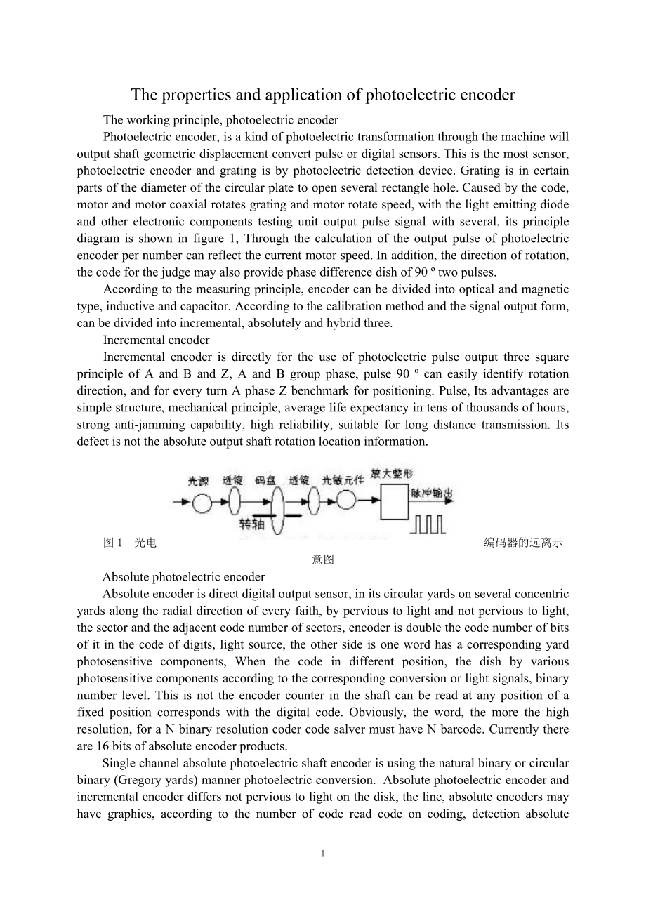
3、 testing unit output pulse signal with several, its principle diagram is shown in figure 1, Through the calculation of the output pulse of photoelectric encoder per number can reflect the current motor speed. In addition, the direction of rotation, the code for the judge may also provide phase diffe
4、rence dish of 90 two pulses.According to the measuring principle, encoder can be divided into optical and magnetic type, inductive and capacitor. According to the calibration method and the signal output form, can be divided into incremental, absolutely and hybrid three.Incremental encoderIncrementa
5、l encoder is directly for the use of photoelectric pulse output three square principle of A and B and Z, A and B group phase, pulse 90 can easily identify rotation direction, and for every turn A phase Z benchmark for positioning. Pulse, Its advantages are simple structure, mechanical principle, ave
6、rage life expectancy in tens of thousands of hours, strong anti-jamming capability, high reliability, suitable for long distance transmission. Its defect is not the absolute output shaft rotation location information.图1 光电编码器的远离示意图Absolute photoelectric encoderAbsolute encoder is direct digital outp
7、ut sensor, in its circular yards on several concentric yards along the radial direction of every faith, by pervious to light and not pervious to light, the sector and the adjacent code number of sectors, encoder is double the code number of bits of it in the code of digits, light source, the other s
8、ide is one word has a corresponding yard photosensitive components, When the code in different position, the dish by various photosensitive components according to the corresponding conversion or light signals, binary number level. This is not the encoder counter in the shaft can be read at any posi
9、tion of a fixed position corresponds with the digital code. Obviously, the word, the more the high resolution, for a N binary resolution coder code salver must have N barcode. Currently there are 16 bits of absolute encoder products.Single channel absolute photoelectric shaft encoder is using the na
10、tural binary or circular binary (Gregory yards) manner photoelectric conversion. Absolute photoelectric encoder and incremental encoder differs not pervious to light on the disk, the line, absolute encoders may have graphics, according to the number of code read code on coding, detection absolute po
11、sition. Code design can use binary code, circulation, binary complement, etc. Its features are:Can read Angle of absolute coordinates directly.No accumulative error. Power excision location information would be lost. But the resolution is determined by the binary digits, i.e., precision depends on t
12、he median 10, 14 etc. Hybrid absolute encoder.Hybrid absolute encoders, its output of two groups: a group of information, information for testing poles with absolute information function, Another group of incremental encoder is completely with the output information.Photoelectric encoder is an Angle
13、 (angular velocity) detection device, it will input shaft Angle for, using the principle of photoelectric convert electrical or digital accordingly, small size, high accuracy, high reliability, digital interface, etc. It is widely applied in nc machine tools, turning machine, servo drive, robots, ra
14、dar and military targets were needed in the Angle of device and equipment.Applied circuit of photoelectric encoderEPC - 755A application of photoelectric encoderEPC - 755A photoelectric encoder and the use of good performance in Angle measurement, displacement measurement, and has strong anti-jammin
15、g capability of the output pulse signal is stable and reliable, and the pulse signal can be obtained by counting were measured after the digital signal. Therefore, we in the car driving simulators, steering wheel rotation Angle measurement chooses EPC - 755A photoelectric encoder, the output circuit
16、 as sensors, choose open collector output resolution selection 360 pulse/circle, considering the steering wheel rotation is a two-way street, clockwise and counterclockwise, can also needs to the output signal phase coder to count. Figure 2 shows the actual use of photoelectric encoder and discrimin
17、ation, phase two-way counts circuit with a D flip-flop circuit and two cross-coupled nand gates, with 74LS193 3 counts circuit.图2 光电编码器鉴相计数电路When the photoelectric encoder clockwise, channel, A leading channel output waveform of output waveform B 90 , D flip-flop output waveform W1) for Q (high leve
18、l, Q (W2) for low-level waveform cross-coupled nand gates, open, counting pulse waveform W3) by (bidirectional, send to the 74LS193 counter CU input pulses, add count, At this time, below, its output cross-coupled nand gates close for high level (waveform W4). When the photoelectric encoder counter-
19、clockwise, channel A output waveform of output waveform delay than channel B 90 , D flip-flop output waveform W1) for Q (low level, Q (W2) for high level waveform, the output cross-coupled nand gates close, high level (waveform W3), Now, two cross-coupled nand gates open, counting under impulsive th
20、rough (waveform W4), send to two-way 74LS193 counter reduced input pulses, CD. Subtraction.Steering wheel clockwise and counter-clockwise, the maximum rotation Angle for two laps, choose resolution for 360 pulse/circle of the output pulse coder, its biggest for 900, Actual use three slices of counts
21、 circuit 74LS193 component in the system of initialization, the signal reset (CLR), the initial set for 800H, namely 2048 (LD); the signal, So, when the steering wheel clockwise, count the output circuit for 2048 2948, when steering counter-clockwise, count the output circuit for 2048-804, D0 output
22、 data counts circuit D11 to data processing circuit.In practice, the steering wheel frequently made clockwise and counterclockwise rotation, because existence, work longer quantization error after a period of time, the steering wheel when the output of a circuit to count, but may not 2048 several wo
23、rds deviation, To solve this problem, we added a steering wheel to detect circuits, systems, data processing circuit after work on the operation state in the simulator, system test in the back, if detection circuit in the back wheel, and counts circuit in the data output, but not to count 2048 reset
24、 circuit, and the initial reset.Photoelectric encoder gravity measurement instrument in the applicationThe rotary photoelectric encoder, the shaft and gravity measuring instrument for knob shaft. Gravity measurement of the angular displacement volume knob compensation for a signal is transformed, Ro
25、tary photoelectric encoder and absolute encoder two points and incremental encoder.Incremental encoder is the output pulse form, its code plate sensor than absolute encoder code easier to disk and higher resolution. Generally need only three barcode, heres code has not actually had word of absolute
26、encoder code, but produce counting pulse. Its code of WaiDao and middle way has the same number of uniform distribution of not pervious to light and sector (raster), but is two sector mutual stagger half area. When the code salver, turning the output signal is A difference for 90 with B in the pulse
27、 signal and only one third of the slit pervious word code generated by the pulse signal (it as the benchmark code salver position, to provide an initial counting system of zero signal). From A, B two output signal phase relationship (ahead or behind) can judge the direction of rotation. Graph 3 by (
28、a), when the code dish is a word, pulse than B ground PI / 2, and reverse, a word than B lagging ways pulses PI / 2. Figure 3. (b) is A practical circuit, use A word of plastic wave along the steady-state produces single trigger word and b are pulse wave phase and plastic disc, when the code is only
29、 positive mouth pulse output, whereas only reverse mouth pulse output. Therefore, the increment of the output pulse coder is according to the source and pulse count to determine the direction and the code salver. Relative angular Usually, if the encoder has N (yards), its output signal phase differe
30、nce of PI/N, may count for the number of times the grating 2N pulse, N = 2. Figure 3 circuit faults are sometimes mistake pulse, this error in a signal in a high or low , and level other signal is in high and low and change of state, though code salver, but will produce a shift in the output pulse.
31、For example, code salver or manual alignment occurs jitter position (below can see, in spring gravimeters measurement will have this kind of case).图3 增量光电编码器基本波形和电路图4 四倍计数方式的波形和电路Figure 4 is a can prevent error and can improve the resolution of the pulse frequency subdivision circuit four times. Her
32、e, the function of memory is D flip-flop and clock generator. Figure 4 shows, by every two D flip-flop, so take in the clock pulse, the interval of two Q end (such as the corresponding B 74LS175 2, 7 foot) maintain two clock period, if both input status, said the change in, Otherwise, can according
33、to the relationship between the changes from the party, which is to or backward output pulse. When a word because of high vibration in the , low , will change between reciprocating alternate positive and backward pulse, the two counter on the number and replace them when they can eliminate the shado
34、w ring (below instrument readings will involve this). Thus, the clock generator frequency of vibration frequency may be greater than the maximum. Can see from figure 4, a pulse signal of the cycle, four counts pulse. For example, the number of every lap pulse coder for 1000 produce four times the nu
35、mber of pulse frequency, and its resolution is 4000 for 0.09 degree. Actually, this kind of sensor products will enlarge the output signal of photosensitive components such as plastic circuit and sensor encapsulation testing components together, so just add subdivision and counts circuit can form a
36、angular measurement system (74159 is 4-16 decoder).Application problem analysis and improvement measuresApplication problem analysisPhotoelectric detection devices transmit and receive devices are installed in the production and use of exposed many defects, its internal factors have external factors
37、, which is mainly embodied in the following aspects:Devices or accept device for mechanical vibration, caused by the shift or offset, receiving devices not reliable to receive light signals, but cannot produce signals. For example, Photoelectric encoder used in steel rolling speed regulation systems
38、, because of photoelectric encoder is bolted directly in motor shell, photoelectric encoder shaft through hard shrapnal and motor rotor connections, because motor with load is a load of impact, while rolling steel rotor motor will have caused the shell and vibration. According to the mensuration, Af
39、ter steel time electricity encoder vibration velocity for 2.6 mm/s, this can damage the vibration velocity of photoelectric encoder internal functions. A pulse, thereby causing instability in control system, or misoperation cause accidents.Because of photoelectric detection device installed in produ
40、ction, production environment factors in photoelectric detection devices not reliable work. Such as the installation position of high temperature, humidity, photoelectric detection device to internal electronic components characteristics change or damage. For example in continuous caster send analyz
41、ed.essential tracking system, because of photoelectric detection equipment installation location near the slab, high temperature environment caused by photoelectric detection device signal or damage caused by accidents or production.Production site for all kinds of electromagnetic interference sourc
42、e photoelectric detection device, of interference, photoelectric detection device of output waveform distortion distortion occurs, the system maloperation accident or production. For example, Photoelectric detection device installed in the production equipment of the signal, the body to the control
43、system of the cable transmission distances in 20-100 meters, cable, although usually choose multiple shielded cable conductor, but due to cable capacitance between lines of resistance and impact plus and other cable laying together, vulnerable to all sorts of electromagnetic interference effect, thu
44、s causing waveform distortion, thus to drive system feedback signal and practical value deviation, and cause the system precision.Measures for improvementChange of photoelectric encoder installation. Photoelectric encoder is not installed in motor shell, but in the motor based on a fixed bracket to
45、independent installation photoelectric encoder, photoelectric encoder axis and motor shaft center must at the same level, two axis adopt soft rubber or nylon hose connection, to reduce the impact of photoelectric encoder motor load of mechanical shock. By this way after vibration testing, the vibrat
46、ion velocity to 1.2 mm/s.Reasonable choice of photoelectric detection device, the output signal transmission medium by twisted-pair cable instead of ordinary shield cable. Twisted-pair cable has two important characteristics of cable, one is by electromagnetic interference with strong protection abi
47、lity, because the space of electromagnetic interference current online can cancel each other out. Twisted-pair cable is another technical characteristics of two mutually twisted line spacing is small, after two lines of interference lines distance equal to two lines, basic capacitance of shielding n
48、etwork basic and same, it is to restrain common-mode interference effect more apparent.Using PLC software to monitor or interference. In the continuous process analyzed.essential photoelectric detection device has the timing signal, at the same time, the whole process of signal and corresponding dif
49、ferent stages. As shown in figure 5.图5 送引锭过程和光电信号关系 1 send analyzed.essential before starting the process, photoelectric signal 1 1. 2 after the start sending analyzed.essential process, in A stage, roller, start sending bar. When the lever block photoelectric device analyzed.essential emit light, t
50、he photoelectric signal for 0, When light guide bar through central 2 small round hole, photoelectric device sends a signal to 2 and 3, 1. 3 analyzed.essential sent in B stage, the process of photoelectric signal for 0, roller suspension bar, stop sending, fan-shaped 10 section pressure straightenin
51、g machine, pull. and 1 , synchronous bar to give. 4 analyzed.essential sent in C stage, process, and no longer bar ceiling light, photoelectric signal four blocks for 1, 2, stop synchronous synchronous 1, lead bar to give. This work is over optoelectronic device.According to the light of electrical
52、device testing work process, as long as the scene of sending analyzed.essential each photoelectric signal process, based on the time analyzed.essential process and photoelectric signal relationship, using PLC application of relevant data, prepare to meet the requirements of PLC program, PLC program
53、output signal input to the input module, instead of PLC original photoelectric signal input signal. The program diagram shown in figure 6. Conclusion Photoelectric detection device is itself by electronic components, it is certain to installation environment of technical requirements, especially in
54、a bad environment, should take corresponding measures to protect the photoelectric detection device to make the product requirements in the work condition, can play the technical characteristics of the device. Otherwise, the service life of photoelectric detection device and reliability of work may
55、be subjected to the influence of different level. Combination of photoelectric detection device in the production process control in the application practice, the design of control system, Using photoelectric detection device is an important signal as the control signal, photoelectric device to avoi
56、d sudden damage or work environment temperature, unstable (large, mechanical vibration, humidity etc) and external touch other equipment accidents. In the application of PLC program control system suitable for process control of reality, to overcome the monitor or interfere with the system adopts ph
57、otoelectric device for the existence of various defects, is to improve the reliability of the system is effective.光电编码器的特性及应用 光电编码器的工作原理光电编码器,是一种通过光电转换将输出轴上的机械几何位移量转换成脉冲或数字量的传感器。这是目前应用最多的传感器, 光电编码器是由光栅盘和光电检测装置组成。光栅盘是在一定直径的圆板上等分地开通若干个长方形孔。由于光电码盘与电动机同轴,电动机旋转时,光栅盘与电动机同速旋转,经发光二极管等电子元件组成的检测装置检测输出若干脉冲信号,其
58、原理示意图如图1所示;通过计算每秒光电编码器输出脉冲的个数就能反映当前电动机的转速。此外,为判断旋转方向,码盘还可提供相位相差90的两路脉冲信号。 根据检测原理,编码器可分为光学式、磁式、感应式和电容式。根据其刻度方法及信号输出形式,可分为增量式、绝对式以及混合式三种。 增量式编码器增量式编码器是直接利用光电转换原理输出三组方波脉冲A、B和Z相;A、B两组脉冲相位差90,从而可方便地判断出旋转方向,而Z相为每转一个脉冲,用于基准点定位。它的优点是原理构造简单,机械平均寿命可在几万小时以上,抗干扰能力强,可靠性高,适合于长距离传输。其缺点是无法输出轴转动的绝对位置信息。图1 光电编码器原理示意图
59、绝对式编码器绝对编码器是直接输出数字量的传感器,在它的圆形码盘上沿径向有若干同心码道,每条道上由透光和不透光的扇形区相间组成,相邻码道的扇区数目是双倍关系,码盘上的码道数就是它的二进制数码的位数,在码盘的一侧是光源,另一侧对应每一码道有一光敏元件;当码盘处于不同位置时,各光敏元件根据受光照与否转换出相应的电平信号,形成二进制数。这种编码器的特点是不要计数器,在转轴的任意位置都可 读出一个固定的与位置相对应的数字码。显然,码道越多,分辨率就越高,对于一个具有 N位二进制分辨率的编码器,其码盘必须有N条码道。目前国内已有16位的绝对编码器产品。绝对式编码器是利用自然二进制或循环二进制(葛莱码)方式
60、进行光电转换的。绝对式编码器与增量式编码器不同之处在于圆盘上透光、不透光的线条图形,绝对编码器可有若干编码,根据读出码盘上的编码,检测绝对位置。编码的设计可采用二进制码、循环码、二进制补码等。它的特点是: 可以直接读出角度坐标的绝对值; 没有累积误差; 电源切除后位置信息不会丢失。但是分辨率是由二进制的位数来决定的,也就是说精度取决于位数,目前有10位、14位等多种。 混合式绝对值编码器混合式绝对值编码器,它输出两组信息:一组信息用于检测磁极位置,带有绝对信息功能;另一组则完全同增量式编码器的输出信息。 光电编码器是一种角度(角速度)检测装置,它将输入给轴的角度量,利用光电转换原理 转换成相应
61、的电脉冲或数字量,具有体积小,精度高,工作可靠,接口数字化等优点。它广泛应用于数控机床、回转台、伺服传动、机器人、雷达、军事目标测定等需要检测角度的装置和设备中。光电编码器的应用电路EPC755A光电编码器的应用EPC755A光电编码器具备良好的使用性能,在角度测量、位移测量时抗干扰能力很强,并具有稳定可靠的输出脉冲信号,且该脉冲信号经计数后可得到被测量的数字信号。因此,我们在研制汽车驾驶模拟器时,对方向盘旋转角度的测量选用EPC755A光电编码器作为传感器,其输出电路选用集电极开路型,输出分辨率选用360个脉冲/圈,考虑到汽车方向盘转动是双向的,既可顺时针旋转,也可逆时针旋转,需要对编码器的
62、输出信号鉴相后才能计数。图2给出了光电编码器实际使用的鉴相与双向计数电路,鉴相电路用1个D触发器和2个与非门组成,计数电路用3片74LS193组成。图2 光电编码器鉴相计数电路当光电编码器顺时针旋转时,通道A输出波形超前通道B输出波形90,D触发器输出Q(波形W1)为高电平,Q(波形W2)为低电平,上面与非门打开,计数脉冲通过(波形W3),送至双向计数器74LS193的加脉冲输入端CU,进行加法计数;此时,下面与非门关闭,其输出为高电平(波形W4)。当光电编码器逆时针旋转时,通道A输出波形比通道B输出波形延迟90,D触发器输出Q(波形W1)为低电平,Q(波形W2)为高电平,上面与非门关闭,其输
63、出为高电平(波形W3);此时,下面与非门打开,计数脉冲通过(波形W4),送至双向计数器74LS193的减脉冲输入端CD,进行减法计数。汽车方向盘顺时针和逆时针旋转时,其最大旋转角度均为两圈半,选用分辨率为360个脉冲/圈的编码器,其最大输出脉冲数为900个;实际使用的计数电路用3片74LS193组成,在系统上电初始化时,先对其进行复位(CLR信号),再将其初值设为800H,即2048(LD信号);如此,当方向盘顺时针旋转时,计数电路的输出范围为20482948,当方向盘逆时针旋转时,计数电路的输出范围为20481148;计数电路的数据输出D0D11送至数据处理电路。实际使用时,方向盘频繁地进行
64、顺时针和逆时针转动,由于存在量化误差,工作较长一段时间后,方向盘回中时计数电路输出可能不是2048,而是有几个字的偏差;为解决这一问题,我们增加了一个方向盘回中检测电路,系统工作后,数据处理电路在模拟器处于非操作状态时,系统检测回中检测电路,若方向盘处于回中状态,而计数电路的数据输出不是2048,可对计数电路进行复位,并重新设置初值。光电编码器在重力测量仪中的应用采用旋转式光电编码器,把它的转轴与重力测量仪中补偿旋钮轴相连。重力测量仪中补偿旋钮的角位移量转化为某种电信号量;旋转式光电编码器分两种,绝对编码器和增量编码器。增量编码器是以脉冲形式输出的传感器,其码盘比绝对编码器码盘要简单得多且分辨
65、率更高 。一般只需要三条码道,这里的码道实际上已不具有绝对编码器码道的意义,而是产生计数 脉冲。它的码盘的外道和中间道有数目相同均匀分布的透光和不透光的扇形区(光栅),但 是两道扇区相互错开半个区。当码盘转动时,它的输出信号是相位差为90的A相和B相脉冲 信号以及只有一条透光狭缝的第三码道所产生的脉冲信号(它作为码盘的基准位置,给计数 系统提供一个初始的零位信号)。从A,B两个输出信号的相位关系(超前或滞后)可判断旋转的方向。由图3(a)可见,当码盘正转时,A道脉冲波形比B道超前/2,而反转时 ,A道脉冲比B道滞后/2。图3(b)是一实际电路,用A道整形波的下沿触发单稳态 产生的正脉冲与B道整形波相与,当码盘正转时只有正向口脉冲输出,反之,只有逆向口脉冲输出。因此,增量编码器是根据输出脉冲源和脉冲计数来确定码盘 的转动方向和相对角位移量。通常,若编码器有N个(码道)输出信号,其相位差为/ N,可计数脉冲为2N倍光栅数,现在N=2。图3电路的缺点是有时会产生误记脉冲造成误差, 这种情况出现在当某一道信号处于高或低电平状态,而另一道信号正处于高和
- 温馨提示:
1: 本站所有资源如无特殊说明,都需要本地电脑安装OFFICE2007和PDF阅读器。图纸软件为CAD,CAXA,PROE,UG,SolidWorks等.压缩文件请下载最新的WinRAR软件解压。
2: 本站的文档不包含任何第三方提供的附件图纸等,如果需要附件,请联系上传者。文件的所有权益归上传用户所有。
3.本站RAR压缩包中若带图纸,网页内容里面会有图纸预览,若没有图纸预览就没有图纸。
4. 未经权益所有人同意不得将文件中的内容挪作商业或盈利用途。
5. 装配图网仅提供信息存储空间,仅对用户上传内容的表现方式做保护处理,对用户上传分享的文档内容本身不做任何修改或编辑,并不能对任何下载内容负责。
6. 下载文件中如有侵权或不适当内容,请与我们联系,我们立即纠正。
7. 本站不保证下载资源的准确性、安全性和完整性, 同时也不承担用户因使用这些下载资源对自己和他人造成任何形式的伤害或损失。
