 发动机转速信号的检测及数字滤波方法

《发动机转速信号的检测及数字滤波方法》由会员分享,可在线阅读,更多相关《发动机转速信号的检测及数字滤波方法(8页珍藏版)》请在装配图网上搜索。
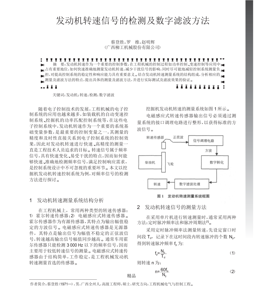
1、.图 1 发动机转速测量系统框图发动机转速信号的检测及数字滤波方法蔡登胜,罗维,赵明辉(广西柳工机械股份有限公司)!摘 要:发动机转速作为一个重要的控制参数,在工程机械的控制过程如功率控制、变速控制等应用中占有重要地位,如何快速准确地测量发动机转速,减少干扰信号的影响,同时尽可能地减轻控制系统测量负 担,对提高控制系统的稳定性和响应能力具有重要意义。结合发动机转速测量系统的结构组成,分析相应的 测量及滤波方法的特点,提出具体的测量及滤波方法,并进行实际测试及滤波效果的验证。关键词:发动机;转速;检测;数字滤波随着电子控制技术的发展,工程机械的电子控制系统的应用也越来越多,如装载机的自动变速控
2、制系统、挖掘机的功率匹配控制系统等,在这些电 子控制系统中,发动机转速作为一个重要的系统基 础变量参数,是最重要的控制变量之一,其测量的 精度和及时性直接关系到电子控制系统的控制效 果,因此对发动机转速进行快速、高精度的测量一 直是工程技术人员追求的目标。转速信号属于频率 信号,具有快速变化、易受干扰的特点,因而如何能 够快速、准确地检测频率信号,满足控制响应需求, 是控制系统设计中不可忽视的重要环节。本文以挖 掘机发动机转速控制系统为例,对频率信号的检测 方法进行探讨。挖掘机发动机转速的测量系统如图 1 所示。电磁感应式转速传感器输出信号必须通过测 量系统的接口调理电路进行整形,以获得标准的
3、方波信号。发动机转速测量系统结构分析1发动机转速信号的测量方法2在工程机械上,常用两种类型的转速传感器:1) 霍尔转速传感器;2) 电磁感应式转速传感器。 霍尔传感器作为有源传感器,其特点为输出幅值稳 定的方波信号。电磁感应式转速传感器是无源器 件,其特点是输出信号为幅值不稳定的正弦波信 号,转速越高输出信号幅值同步越高。通常车用霍 尔传感器只能检测 3 000 Hz 以下的频率信号,因而 主要用于较低转速信号的测量。电磁感应式转速传 感器由于结构简单,工作稳定,是工程机械发动机 转速测量首选的传感器。在采用单片机进行转速测量时,通常采用两种方法:定时脉冲频率法和脉冲周期法1。采用定时脉冲频率
4、法测量转速,先设定窗口时 间段 Td,记录下在这时间段内转速脉冲的个数 Np, 得到转速脉冲频率 fp 为:f = Np (1)pTd则转速 n 为:n= 60fp(2)Ng作者简介:蔡登胜(1971),男,广西全州人,高级工程师,硕士,研究方向:工程机械电气与控制工程。!精品.工程机械第 43 卷 2012 年 11 月Test and Research式中:Ng 为测速齿轮的齿数。从转速计算公式可知,时间 Td 为准确值,测量 的精度主要取决于脉冲计数 Np 的误差。定时脉冲频率法测量方法简单,但由于窗口时间段 Td 不可能与脉冲整数周期完全重合,存在起始脉冲和最后一个 脉冲丢失的可能,当
5、待测信号频率较低时,若窗口 时间段较短,则测量误差较大。脉冲周期法是通过单个脉冲的周期来计算转 速的方法。采用脉冲周期法测量转速,实际上是以 每个脉冲周期为窗口时间段,统计控制器 CPU 的定 时器在这一窗口时间段内得到的计数值 Ncc,则这个转速脉冲的周期 Tp 为:二是及时性。若只考虑测量精度,加大样本量是提高精度的最重要的手段,而加大样本量所导致的延 时则必然影响数据的及时性,因此必须找出发动机 转速的特点,在有限的时间内,将测到的异常信号 滤除,从而及时获得所需要的精确转速信号。通常的数字滤波方法有均值滤波、中值滤波和 限速(限幅)滤波等。3.1 均值滤波算术均值滤波是将所有采样值求和
6、后除以样 本数,而加权均值滤波是在求和之前对每个采样值 赋给一个权重系数 ai,均值滤波计算公式为:nX軍= 1 aiXi(5)Tp= Nccn i = 1(3)fc式中:fc 为 CPU 基准计数频率。则转速为:对算术滤波,式中的 a =1。从均值滤波的定义可i以看出,均值滤波并不能够将干扰排除,而是将干扰分散,使数据的变化变得平滑一些。3.2中值滤波 中值滤波是指将一组数据队列的中值作为滤波结果输出值的滤波方法。中值滤波计算方法为:将连 续采样得到一组样本数据 x1,x2,xn,按从小到大(或从大到小)的次序进行排序,排序后的数据按次 序依次为 y1,y2,yn。若样本个数 n 为奇数,则
7、中值 滤波结果为:60(4)n=Ng Tp可以看到,与定时脉冲频率法一样,测量精度与时钟频率 fc 和待测信号频率有关,在 fc 远远大于 转速脉冲的频率时,可以取得较高的精度。工程机械用发动机转速通常在 6502 500 r/min的范围,采用脉冲周期法测量结果精度会更高。由于发动机转速信号检测电路属于弱电电路, 在封闭的车载电气系统上,极易受到电磁干扰,从 而导致测量结果出现干扰误差,另外,由于在采用 脉冲周期法进行转速测量时,实际上得到的是一个 个测速齿经过转速传感器时的瞬时转速,而对发动 机来说,在曲轴转动一周的过程中转速并不是均匀 的,因此在采用脉冲周期法测量转速时,必须考虑 上述两
8、种情况造成的测量误差。对于信号的失真,可以通过硬件电路和软件算 法进行处理,硬件电路通常是采用低通滤波的方法 进行处理,将高于正常转速的频率信号进行滤除, 在此不再赘述。由于电子元件参数的分布影响,硬 件滤波的方法通常无法精确地将所有高于正常转 速的频率信号滤除掉,因而必须通过软件滤波算法 进行滤波。M(x)=y(n+1)/2若样本个数 n 为偶数,则中值滤波结果为:(6)M(x)= yn/2+y(n+2)/2(7)2中值滤波由于去掉了极大、极小值,对偶发干扰具有较好的滤波效果,但连续采样的数据数量越大, 排序计算量就越大,对控制系统的运算速度要求也 越高。3.3限速(限幅)滤波限速(限幅)滤
9、波属于一种经验滤波,主要算法为:将本次采样值 x 与上次采样值 x的变化量的nn- 1绝对值,与预设最大允许变化量 x 进行比较,如果小于或等于 x,则取本次采样值为当前值,若大于 x,则丢弃本次采样值,取上一次的采样值作为当 前值,计算公式为:Xn=Xn-1, xn -xn- 1Xn=Xn,xn -xn- 1x 转速信号的数字滤波算法在进行数字滤波设计时,首先必须清楚控制系 统对发动机转速测量的要求,即控制系统的所有控 制变量因子都必须达到两点基本要求:一是精度,3(8)x 限速滤波的难点在于 x 的选择,若 x 取值太大,则无法将干扰滤除,若 x 取值过小,则无法 20 精品.工程机械第
10、43 卷 2012 年 11 月Test and Research反映真实的信号变化。对数字滤波来说,采样数据量越大,则抗干扰能 力越强,滤波后的数据平滑性也越好,但考虑到采样 数据量越大,则所需时间越长,对系统的响应速度是 不利的。根据控制系统对采样变量的两个要求:精 度和及时性,必须对两者进行平衡。为加大采样数据量,并尽可能减少数据采集时 间对及时性的影响,通常可以采用 FIFO(先进先出) 的数据处理办法,即一组包含 n 个数据 x1,x2,xn 的采样数据集,若有新的采样数据 xn+1,则将最先测 到的 x1 去除,使采样数据集依然保持为 n 个数据, 以此类推,采用 FIFO 的样本
11、数据处理方法,可以改 善数据的平滑性。发动机转速的实际滤波设计挖掘机发动机的转速主要通过检测飞轮转速来 获得。对于飞轮齿数为 Ng 的发动机,转速脉冲信号 的频率为:4f= Ng n (9)60若飞轮齿数 Ng 为 127 齿,发动机的正常转速 n为 6502 500 r/min,根据式(9),正常转速检测信号 的最低频率为 1 375 Hz,最高频率为 5 292 Hz。要对这样的频率信号进行检测,根据前文分析, 采用脉冲周期法对转速传感器信号进行采样,采样 结果如图 2 所示。图 2 是采用脉冲周期法测量到发动机的 500个瞬时转速值,图中纵坐标为转速,横坐标为采样 数。实际上每一个采样得
12、到的转速都是测速齿经过转速传感器时的瞬时速度,图 2 显示出在发动机旋转一圈(即任意 127 个采样)中,实际上转速并不是 均匀的,并且变化还相对较大,在固定油门及负载无变化的情况下,500 个采样得到的最大瞬时转速 为 2 105 r/min,最小瞬时转速为 2 079 r/min,最大的 瞬时速度比最小瞬时转速高出 26 r/min,即在系统 无变化的情况下,测到的转速值在不断地波动,这 一波动会造成控制系统输出的扰动,必须通过滤波来消除这样的干扰。假设不存在干扰的情况下,按照发动机旋转一 圈的齿数选取每次 127 个脉冲作为当前采样进行 FIFO 算术平均滤波,得到 127 位 FIFO
13、 算术平均滤 波结果如图 3 所示。图 3 显示,通过 127 位算术平均滤波后,得到转速为 2 0902 092 r/min,只有 2 r/min 的波动,说 明以整转脉冲个数作为样本数据集进行算术平均滤波,对转速周期性的波动可以取得较好的滤波效果。在采用脉冲频率法进行转速测量时,通常采用中 断捕捉方式测量每个转速信号的周期,测量过程需占 用系统时间,若每次捕捉 127 个脉冲,按 2 090 r/min 的转速来计,捕捉 127 个脉冲约需 28 ms,这对一个 控制系统来说周期太长了,因此必须寻找到较短时间 来获得同样或近似的滤滤效果。为缩短采样时间,采用每次采样 8 个脉冲进行 分段算
14、术平均滤波,滤波效果如图 4 所示。从图 4 来看,缩短了采样中断时间后,8 位分段 算术平均滤波效果并不明显,仍是按照与原始瞬时 转速相同的趋势在波动。 21 精品.图 3 发动时瞬时转速与 127 位 FIFO 算术平均滤波结果图 4 瞬时转速与 8 位分段算术平均滤波结果工程机械第 43 卷 2012 年 11 月TestandResearch若保持相同的中断采样时间,采用 8 位分段中值滤波算法进行滤波,所获得的滤波效果如图 5所示。从图 5 来看,缩短了采样中断时间后,采用 8 位分段中值滤波算法与采用 8 位分段算术平均滤 波效果基本一样,无法消除周期性的波动,因此,要 增大采样数
15、,同时保证较短的采样时间,避免占用 过多的 CPU 资源,必须采用组合滤波方法。试图对 8 位原始采样信号在进行分段算术滤 波、分段中值滤波后再进行二级滤波。在二级滤波 时,由于没有 CPU 资源过多占用的担忧,通过两级滤波取得更多的采样信号。以下对算术滤波法与中 值滤波法分别组合形成的二级滤波效果进行分析 研究。图 6 为一级 8 位分段算术平均滤波加二级 8位中值 FIFO 滤波的滤波效果,图 7 为一级 8 位分段中值滤波加二级 8 位分段算术平均滤波的滤波 效果,图 8 为一级 8 位分段中值滤波加二级 8 位FIFO 算术平均滤波的滤波效果。从图 6、图 7 和图 8 可以看出,采用
16、两级滤波 后,不论是哪一种滤波组合,其滤波效果与单级 127 位滤波效果基本相同。在第一级滤波中采用中值滤波,更能排除转速的瞬时波动,同时考虑到在实际 工作时,转速信号的采样是间隔进行的,在二级滤 波中采用 FIFO 算术平均滤波,得到的转速更平滑, 并且采用 FIFO 还可以根据控制的需要,随时获得足够的一级滤波值来进行二级滤波,从而获得更好 的及时响应能力。因此,在一级滤波时采用 8 位分 段中值滤波,在二级滤波时采用 8 位 FIFO 算术平 22 精品.图 5 瞬时转速与 8 位分段中值滤波结果图 6 一级 8 位分段算术平均滤波二级 8 位中值 FIFO 滤波效果图 7 一级 8 位
17、分段中值滤波二级 8 位分段算术平均滤波效果工程机械第 43 卷 2012 年 11 月TestandResearch 23 精品.图 8 一级 8 位分段中值滤波二级 8 位 FIFO 算术平均滤波效果工程机械第 43 卷 2012 年 11 月TestandResearch均滤波得到的结果与 127 位的大数据量滤波效果更接近,转速曲线更平滑。滤波,能获得比较理想的结果。就其他工程机械发动机转速测量而言,采用两级组合滤波方式也是可 以的,但究竟采用哪种组合滤波方式能更好地满足 控制要求,尚待进一步分析探讨。结束语本文分析了挖掘机发动机转速的测量系统,对 转速的测试方法及滤波方法进行了探讨,
18、并针对发 动机转速的不均匀性,结合控制系统对转速存在的 测量精度和及时性要求,提出了分段中值滤波和 FIFO 算术平均滤波两级滤波的转速滤波方法,以在 降低单片机资源占用的情况下,获得较好的检测及 时性及测量精度。对挖掘机发动机转速测量而言,采用图 8 所示 的方案,即数字滤波采用两级组合滤波方式,一级 为 8 位分段中值滤波,二级为 8 位 FIFO 算术平均5参考文献1 蒋东方.基于边沿捕捉与中值滤波的航空发动机转速测 量J.仪表技术与传感器,2009(2):96- 99.2 王保强,窦文,白红.高精度测频方案设计J.成都信息工 程学院学报,2002(2):77- 81.3 王庆河,王庆山
19、.数据处理中的几种常用数字滤波算法J.计量技术,2003(04):53- 54.通信地址:广西柳州市柳太路 1 号 广西柳工机械股份有限公司中央研究院(545007)(收稿日期:2012- 07- 11)!(上接第 5 页)标准化工作,使我国节能型土方机械和再制造产品 得到全面的提高和发展,使土方机械产品的制造资 源消耗和产品应用中的能源消耗得到显著的降低。(5)重点研制和实施土方机械安全和环境保护 标准。土方机械的安全和环保是国际土方机械产品 发展的重点以及标准制定的重点,因此我国要重点 研制和实施土方机械安全和环境保护标准,重点实 施和修订完善 15 项土方机械安全以及土方机械噪声限值的强
20、制性国家标准。通过制定和实施这些起点较高,符合当前世界土方机械发展方向的标准, 提升我国土方机械产品的技术含量,构成对人身安 全、身体健康及社会环境的全面、系统的保护和保 障,增强我国土方机械产品的国际竞争力。通信地址:天津北辰科技园区华实道 91 号 天津工程机械研究院(300409)(收稿日期:2012- 09- 05) 24 精品.IAbstracts in Englis(Serial No. 469)PI1I)lishing on Nov. 10, 2012Vol. 43No. IIPresent Situation and Analysis of Chinese Standardof
21、 Earthmoving Machineryapplication of the process and the basic workrequirements etc, job instances prove that the shoot blaster and its process can meet the application with satisfactory results. Therefore, we should suggest to promote in full the shoot blasting for pavement surface treatment within
22、 China.Keywords: Pavement; Shot blasting treatment;The textintroduces Chinese national standards ofcarthmoving machinery together with the industrial basisand situation while analyzing formation, distribution, quantity and quality of the standardization system as well as differences with ISO and oth
23、er foreign standards. More, the text in view of defects andlor backwards in some of the standards analyzes their suitability and aging effects before putting forth stresses on the jobs to come concerning standardization of the earthmoving machinery, which line up as to raise suitability of the stand
24、ards with the market, to adopt effective measures to utilize ISO standards, to readjust composing elements ofthe national standards so as to set up important pieces ofSurface roughness; Adhesionbinding; Work processandBrief Discussion on Profile of Loader BucketFirst of all, function and significanc
25、e of loaders bucket profile and design should be clearly defined, before discussing how the bucket is classified, and the major parameters that affect the loading performance. The next step is to introduce how the loader bucket was designed,according to the present experiences. And finally, thestand
26、ard. topromote research and development in thesurrounding the StatesnatIonaI standardization asfor industrial readjustment indprogramstogetherdiscussion touchesrcle ant theoriesand criticaleflCtiN/Ifl1.with low carbon economy, and to focus ontechniques in the bucket profile and design.Keywords: Load
27、er; Bucket; Bucket profile designceculIon ot aIct andresearch and de cIoiiciit andenvironmentmachinery. Keywords:friendly standards for the earthmovingBrief Analysis of Backlash Adjustment for SlewingMechanismThe text introduces mesh lashes of the swing reduction pinion with the swing circle gear pl
28、us the affecting factors and how to readjust. Through formula deduction we got that eccentric arm of the swing reduction gear and angle of the actual installation as relative to that of its initial installation does affect side lashes at the gear pair. Keywords: Swing reduction gear; Gear backlash;A
29、djustmentmachinery; Standard;EarthmovingAnalysisModel GYSPW2O8O Shot Blaster and Shot BlastingTreatment ProcessesTo treat road and bridge surface with shoot blasting becomes a newcomer advanced process to deal with problems in the local surface traffic for the recent several years. However, to execu
30、te this process needs a special piece of equipment for the job, i.e. a shoot blaster to trim the pavement surface. The text beginning with basic working principles of the shot blaster introduces the model GYSPW2O8O shot blaster plus its make-up, basicfeatures, critical techniques, as well as range o
31、fEngine Speed Signal Testing and Method of DigitalFilteringThe engine RPM as an important parameter in the construction machinery controls in a process, e.g. power精品.IAbstracts in Englis Icontrol, speed change and control. Therefore, it is ofimportant significance to quickly and precisely measure ou
32、t the RPM and minimize affection by the interference signals while reducing measurement loads as much as possible at the control system so as to increase stability and respondent capability of the control system. We considered structural formation of the RPM measuring system with analyses of the cor
33、respondent measurements and filtering methods before put forth concrete measurements and filtering methods while verifying actual tests and filtering results.Keywords: Engine; RPM; Test; Digital filteringstraight travel performance of the roller itself. Therefore,we tested vibratory amplitude along
34、tread of the single drum vibratory roller and found serious bias-vibration existing there at 8.8% bias-vibration amplitude at high vibration rate, and 7.6% at a lower vibration rate. We according to structural parameters of the single vibratory drum roller set up an ADAMS model for the vibratorydrum
35、 while simulating vibratory amplitude evenness ofthe vibrating drum, thus effectively improvingbiasvibration of the vibratory roller by means of minimizingbias displacement of energizing center in the vibratory drum as off mass center of the vibratory body. Keywords: Vibratory compactor; Deflectivev
36、ibration; Test; ADAMS; SimulationShaft Modal Analysis of Power System of HybridPower ExcavatorsWe through finite element computation had got top 10Cooling System of aLoader6-ton Energy-Saving Typeof modular frequency and vibrationmode,gradesrespectively, for the diesel engine shaft series and themot
37、or shaft series. Thereon, we through finite element computation had got top 10 grades of modular frequency and vibration mode, respectively, for the mixed power shaft series. Computation results show that as compared with common power systems there is a decrease of individual modular frequencies in
38、the mixed power shaft series as a result of the electric motor insertion, buthigher than that of the electric motor shaft series. Such aIt introduces a 6 t power saving type wheel loader as anproduct of the Tianjinresearch and developmentResearch Institute of Construction Machinery itself. Theresear
39、ch and development indcpendent radiating-cooling system consists of a fan, fixed displacement pump, fixed displacement motor, proportional relief valve, temp sensor, temp control valve, monitors, etc. The cooling fan is driven through an independent controllable hydraulic system and a fuzzy control
40、way so as to cool down simultaneously the 3 media of engine coolant, hydraulicoil, and the torque converter oil. The systems featuresdecrease is mainly because of grades ofmodularfrequency in the electric motor shaft series are obviouslyhigher than that of the diesel engine shaft series, which was f
41、ollowed by a trial test and analysis of the vibration signals at the mixed power shaft series. Test results show that signal energy concentrates in the X direction and Y direction and tell that the vibration signal is mainly created by the bending vibration. Frequency spectrum of the vibration signa
42、l witnessed 5th-grade and 6th grade modular frequency in shaft series of the power system and tells that the vibration signal comes mainly fromrotor of the electric motor.include simpleconstruction,precise control, easyoperation, safety and reliability, quick temp raise of thecooling medium, stable
43、functions and performance.fan;Keywords:Loader;CoolingProportionalrelief valve; Fuzzy controlStrength Finite Element Analysis ofDrive ShaftBulldozerA finite element model was set up by utilizing ANSYSWorkbench software for the steering clutch input shaft in a certain type bulldozer under a turning to
44、rque load while carrying out a finite element analysis thereof to have got stress and strain results at dangerous positions of the drive shaft. The results show that failures are vulnerableto happen at positions of the spline and/or transit radius.excavator;powerPowerShaftKeywords: Hybridsystem; Modularseriesanalysis;Deflective Vibration Simulation Analysis of SingleDrum Vibratory Compactors Based on ADAMS Deflective vibration in the vibratory compactor does not only affect evenness of the compaction but also affectDriveshaft;Torqueload; FiniteKeywords:elementr如有侵权请联系告知删除,感谢你们的配合!精品
- 温馨提示:
1: 本站所有资源如无特殊说明,都需要本地电脑安装OFFICE2007和PDF阅读器。图纸软件为CAD,CAXA,PROE,UG,SolidWorks等.压缩文件请下载最新的WinRAR软件解压。
2: 本站的文档不包含任何第三方提供的附件图纸等,如果需要附件,请联系上传者。文件的所有权益归上传用户所有。
3.本站RAR压缩包中若带图纸,网页内容里面会有图纸预览,若没有图纸预览就没有图纸。
4. 未经权益所有人同意不得将文件中的内容挪作商业或盈利用途。
5. 装配图网仅提供信息存储空间,仅对用户上传内容的表现方式做保护处理,对用户上传分享的文档内容本身不做任何修改或编辑,并不能对任何下载内容负责。
6. 下载文件中如有侵权或不适当内容,请与我们联系,我们立即纠正。
7. 本站不保证下载资源的准确性、安全性和完整性, 同时也不承担用户因使用这些下载资源对自己和他人造成任何形式的伤害或损失。
最新文档
- 幼儿园绘本故事当我睡不着的时候课件
- 人教版小学五年级品德与社会上册《五十六个民族五十六朵花》ppt课件
- 人教版小学一年级音乐下册红眼睛绿眼睛ppt课件
- 人教版小学数学四年级上册《数学广角》ppt课件
- 幼儿园优质课件小猫的生日
- 幼儿园科学活动区创设与材料投放课件
- 人教版小学四年级音乐小螺号ppt课件
- 幼儿园科学教育的方法和途径课件
- 开盘前广告策略案课件
- 人教版小学一年级品德与生活《校园铃声》ppt课件
- 人教版小学五年级音乐吹起羌笛跳锅庄ppt课件
- 人教版小学四年级英语下册unit3_weather第三课ppt课件
- 人教版小学一年级上册数学第二单元上下前后ppt课件
- 人教版小学五年级美术第17课电脑动画ppt课件
- 幼儿园优质课件-幼儿园中班“我们都是好朋友”课件
