 机械外文翻译 电梯基础知识-4_电梯机房井道和底坑

《机械外文翻译 电梯基础知识-4_电梯机房井道和底坑》由会员分享,可在线阅读,更多相关《机械外文翻译 电梯基础知识-4_电梯机房井道和底坑(33页珍藏版)》请在装配图网上搜索。
1、4 电梯机房、井道和底坑Machine room,Well and pit of lift4-1机房Machine room电梯机房一般设置在电梯井道的顶部(机房上置式)。机房内安装有曳引机、导向轮、控制柜、限速器、总电源控制盒等。Normally located on top of well (upper-placed machine room), machine room includes traction machine, diverter pulley, control cabinet, overspeed governor and main power control box.4-1
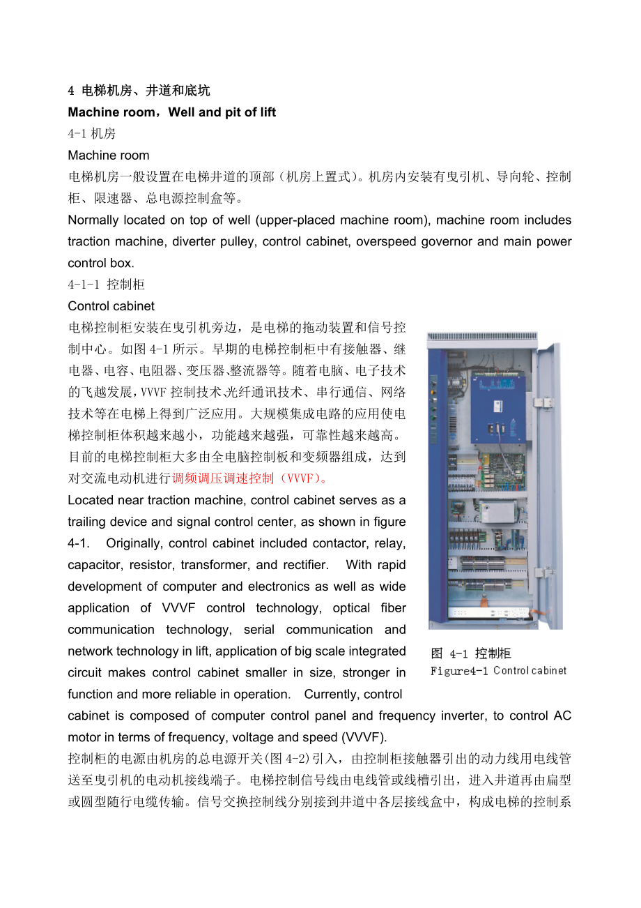
2、-1 控制柜Control cabinet电梯控制柜安装在曳引机旁边,是电梯的拖动装置和信号控制中心。如图4-1所示。早期的电梯控制柜中有接触器、继电器、电容、电阻器、变压器、整流器等。随着电脑、电子技术的飞越发展,VVVF控制技术、光纤通讯技术、串行通信、网络技术等在电梯上得到广泛应用。大规模集成电路的应用使电梯控制柜体积越来越小,功能越来越强,可靠性越来越高。目前的电梯控制柜大多由全电脑控制板和变频器组成,达到对交流电动机进行调频调压调速控制(VVVF)。Located near traction machine, control cabinet serves as a trailing
3、device and signal control center, as shown in figure 4-1. Originally, control cabinet included contactor, relay, capacitor, resistor, transformer, and rectifier. With rapid development of computer and electronics as well as wide application of VVVF control technology, optical fiber communication tec
4、hnology, serial communication and network technology in lift, application of big scale integrated circuit makes control cabinet smaller in size, stronger in function and more reliable in operation. Currently, controlcabinet is composed of computer control panel and frequency inverter, to control AC
5、motor in terms of frequency, voltage and speed (VVVF).控制柜的电源由机房的总电源开关(图4-2)引入,由控制柜接触器引出的动力线用电线管送至曳引机的电动机接线端子。电梯控制信号线由电线管或线槽引出,进入井道再由扁型或圆型随行电缆传输。信号交换控制线分别接到井道中各层接线盒中,构成电梯的控制系统线路。在控制柜和机房布线时要注意强弱电要分开,防止弱电受干扰。Power supply of control cabinet is introduced from the main power supply in machine room(figure
6、 4-2 ). Cable leads from the contactor of control cabinet to the motor terminal of traction machine via conduit. Derived by conduit or channel, lift control signal line enters well then is transmitted by flat or round traveling cable. Signal exchange control lines are connected to terminal boxes of
7、each landing in well, forming lift control loop. It is requiredthat power line and weak signal be separated to prevent weak signal from being interfered with when wiring is made in control cabinet and machine room. 4-1-2 曳引机Traction machine详情已在第二章(曳引机)描述。The details has been described in chapter 2 (
8、Traction machine).4-1-3 限速器Overspeed governor限速器一般装在机房的地面上,曳引机旁边(图4-3), 其工作原理见5-2章。Governor is installed on the ground of machine room, at the side of machine (figure 4-3). The working principle will be de scribed in chapter 5-2.4-2电梯井道Well电梯井道是由井道壁、井道顶面和底面组成的,是供电梯轿厢和对重运行的空间,通常位于建筑物的内部,一般是由混凝土、砖或钢结构
9、构成,并具有足够的机械强度。Composed of well wall, well top and well bottom, well is always located inside the building as moving space for car and counterweight. It is made of concrete, brick or steel so as to bear mechanical strength. 4-2-1 导轨Guide rail导轨(图4-4):用于轿厢和对重在垂直方向运动时的导向,并限制轿厢和对重在水平方向的位移。轿厢和对重应至少有两根刚性的
10、钢制导轨导向。导轨通常用冷扎T型钢制成,其抗拉强度应为370520N/m2之间。导轨设计时主要考虑以下因素:载有不均布载荷沿导轨运行时;安全钳动作时;装载或卸载时。导轨强度主要考虑安全钳动作时,导轨的抗拉强度,导轨的变形则考虑载有不均布载荷沿导轨运行时。Guide rail(figure 4-4): it is used to guidecar and counterweight in vertical directionand restrict their horizontal displacement.Car and counterweight should have at leasttw
11、o rigid steel rails. Guide rails are alwaysmade of cold-rolled T-steel, whose anti-pullstrength should range from 370 N/m2 to 520N/m2. Following conditions should be taken into consideration when guild rails aredesigned. When unevenly-distributed load is imposed on rail;When safety gear is activatin
12、g;When loading or unloading is under way;Guide rail strength, especially anti-pull strengthshould be considered when safety gear isactivating, while rail deformation should be considered when uneven load is moving on rail.4-2-1-1 导轨与导轨的连接Connections between rails每根导轨的长度一般为45m,在安装时端部以榫头与榫槽配合定位,底部用连接板
13、固定,榫头与榫槽具有很高的加工精度,起连接定位作用,接头处的强度由连接板和连接螺栓保证,连接后接头处不应存在连续缝隙,并且接头处应平滑,必要时进行修光。见图4-5。Usually each guide rail is 4m to 5m long. When mounted, guide rails are connected to each other and fixed by wedge and wedge groove on both sides. Its bottom is fixed by connecting board. Featuring highly processing pr
14、ecision, wedge and groove serve to connect and fix; strength of joint is guaranteed by connecting board and bolts. After connection is completed, no continual gap should exist in joint and joints should be smooth, if necessary, polished. See figure 4-5.4-2-1-2 导轨架Rail support导轨通过导轨架与井道壁连接。轿厢导轨架通常是可调
15、的,以保证导轨之间的距离,见图4-6。导轨的承载能力与导轨架配置间距有关系。同一规格的导轨当导轨架配置间距较小时,可获得较大的承载能力。导轨架的配置间距通常为2.5m,根据实际情况缩小或扩大,其要求是导轨在工作中的挠度不应超过允许挠度。Rails are connected with well wall by means of rail support which is usually adjustable to ensure specific distance between rails,see figure 4-6. Support capacity of rail is related
16、to the distance between rail supports. For rail with same specifications, the shorter the distance between rail supports is, the larger the support capacity is. The distance of rail supports is normally , which can be decreased or increased according to actual circumstances; however, bending deflect
17、ion for rails must not exceed maximum allowed value of .4-2-1-3 导轨压板Rail clip导轨架与导轨的连接通过压板(图4-7),压板有浮动型和模锻型,浮动型压板可减少由于导轨应力产生的导轨变形,导轨的应力来自于导轨的热胀冷缩和不可避免的建筑物下沉。当导轨应力克服了压板摩擦力后,导轨可以沿纵向伸缩,减少了导轨的受力变形,增加了电梯的安装质量。模锻型压板主要用于固定隔光板的支架,极限开关的支架等,使这些支架不至产生移位。Rail supports are connected with rails by means of rail c
18、lip (figure4-7), which is classified into floating and mold-cast types. Floating type can protect rails from deformation caused by the intrinsic energy of rails, which derives from rail expansion and constriction due to temperature change as well as unavoidable precipitation of building. After the i
19、ntrinsic energy overcomes friction of boards, rails can extend vertically to reduce deformation and improve lift installation quality. Mold-cast type is mainly used to fix sensor vane and final limit switch brackets to avoid their displacement.4-2-2导靴 Guide shoe导靴是为了防止轿厢在曳引绳上的扭转和不对称负载下的偏斜,使电梯的轿厢、对重沿
20、着导轨上下移动的导向装置,当轿厢与对重的悬挂中心不变时,导靴几乎不受力。由于载荷的移动总是使轿厢中心发生变化,由此产生的力就反映在导靴上,使导靴靴衬随着电梯上下运行而磨损。Preventing car from wiggling on traction rope or deviating under uneven load, guide shoe is used to make car and counterweight move along rails. If suspension center of car and counterweight is constant, almost no
21、force is applied on guide shoe. Since load movement always leads to the change of car center, force produced will be reflected on guide shoe, making guide shoe lines worn out with lift moving upwards and downwards.4-2-2-1 导靴的安装位置Mounting position of guide shoe每台电梯的轿厢共安装四套沿导轨滑动或滚动的导靴,安装在轿厢轿架的四个角与导轨接触
22、处,两套上导靴固定在轿厢上梁上,两套下导靴固定在安全钳钳座上。每台电梯的对重侧安装四套导靴,安装在上、下横梁两侧端部。Car is equipped with four sets of sliding or rolling guide shoes that are located in the overlapping area of the four angles of car frame and rails; to be specific, two sets are fixed on top transoms, while the remaining on safety gear seat.
23、 Counterweight side is equipped with four sets of guide shoes that are located on both sides of top and bottom transoms. 4-2-2-2 导靴的种类Types of guide shoe电梯导靴基本上分为三大类。Guide shoe is classified into three types.4-2-2-2-1 固定式滑动导靴Fixed sliding guide shoe常用于低速载货电梯上。固定式滑动导靴只能用在电梯运行速度V/s的电梯轿厢或对重上。此类导靴的靴头是固定
24、死的,没有调节的余地。因此,导靴与导轨之间存在一定的间隙,随着运行时间的增长,间隙会越来越大,电梯运行中会出现晃动。保养时常常需要用黄油润滑导轨。图4-8所示是固定式滑动导靴的一种Suitable for low-speed cargo lift, fixed sliding guide shoe can only be used in car or counterweight of lift with V/s. The shoe head is fixed with no room to adjust. With running time accumulation, the gap betw
25、een shoe and rail will be increasingly large, therefore, lift will swing during operation. Butter should be used to lubricate rails for maintenance. One of the fixed sliding guide shoes is shown in figure 4-8.4-2-2-2-2 弹性滑动导靴Elastic sliding guide shoe弹性滑动导靴由靴座、靴头、靴衬、靴轴、压缩弹簧、调节组件组成。要求其靴衬以适当的压力与导轨表面接触
26、(压力可调整到基本上浮动状态为宜)。这类导靴必须在其上部带机油油杯,在电梯运行时机油通过导油毛毡不断润滑导轨。弹性导靴的靴头只能在弹簧的压缩方向上作轴向移动。与固定式滑动导靴不同的是靴头是浮动的。靴衬的底部始终紧贴在导轨的工作面上,吸收电梯运行中产生的振动与冲击。为了补偿导轨侧工作面的直线偏差,导靴与导轨工作面之间要留有一定的间隙。这种导靴的应用范围一般在V图4-9所示是弹性滑动导靴的一种。Elastic sliding guide shoe is composed of shoe saddle, shoe head, shoe lines, shoe shaft, compressing s
27、pring and adjusting parts. It is required that shoe lines contact rail surface by proper pressure (pressure is assumed proper that is adjusted to floating state). Such guide shoe must have oil cup on its top so as to lubricate rails continuously by means of felt during lift operation. Shoe head can
28、only move axially along spring compression direction. Unlike fixed sliding guide shoe, its shoe head is floating. Constantly attached to working surface tightly, the bottom of shoe lines absorbs shock produced during lift operation. To offset lineal deviation of rail side working surface, there shou
29、ld be a specific gap between guide shoe and rail working surface. Such guide shoe is used in lifts with V/s. One of the elastic sliding guide shoes is shown in figure 4-9.4-2-2-2-3 滚轮式导靴Rolling guide shoe滚轮式导靴如图4-10所示,它是由滚轮、弹簧、靴座、摇臂组成。滚轮式导靴以滚轮代替了滑动导靴的三个工作面,三个滚轮在弹簧力的作用下,紧贴在导轨的三个工作面上,见图4-11。导靴三个滚轮浮动地压
30、住导轨三个工作面,可消除电梯运行时产生的振动和噪音,当电梯运行时,滚轮在导轨上滚动,大大减小了运行的摩擦力,使电梯运行平稳、舒适、噪音小、节约能源。在导轨上的压力与弹性导靴相同,并通过调节弹簧力对滚轮的压缩量进行调节。Rolling guide shoe is shown in figure 4-10,it is composed of roller, spring, saddle androtating arm. Replacing three workingsurfaces, three rollers are attached to threeworking surfaces of ra
31、il under the spring force, see figure 4-11 . Three rollers press three working surfaces of rail, to eliminate shock and noise during lift operation. With low noise and economical power consumption, rollers move on rails, reducing friction greatly to ensure stable run and comfortable ride. Pressure o
32、n rail is same as that of elastic guide shoe, besides, compression of rollers can be adjusted by means of spring.滚轮式导靴绝对不允许在导轨的工作面上加润滑油。否则,会使滚轮打滑,无法运转。因此,滚轮导靴的另一个优点是不用给导轨加油,无油污染。For roller guide shoe, lubricant must not be used on rail working surface; otherwise, roller will slip so as to fail runni
33、ng. Therefore, roller guide shoe has no oil pollution. 滚轮导靴常用在电梯速度V2.0m/s的高速电梯上。Roller guide shoe is usually used in high-speed lift with V/s. 为了降低运行噪音,减小摩擦力,尽量可以采用大一点的滚轮直径。如电梯速度为5m/s时,轿厢侧的导靴滚轮直径至少为250mm,对重侧的导靴滚轮直径至少为150mm;当电梯速度为2.5m/s时轿厢导靴滚轮为150mm,对重导靴滚轮为75mm。To reduce running noise and friction, i
34、t is recommended roller have larger diameter. For lifts with speed of 5m/s, roller diameter should be at least 250mm for car side, 150mm for counterweight side; for lifts with speed of /s, roller diameter should be at least 150mm for car side, 75mm for counterweight side; 4-2-3 隔磁板或隔光板(平层桥)Magnetic-
35、isolating or light-isolating plate (sensor vane) 平层桥安装在电梯井道内每个层站平层区域内。当轿厢运行到某一平层区时,该平层桥插入轿厢顶上相应的感应器内,切断感应器磁(或光)回路,发出信号给控制柜,从而控制电梯平层停车开门。平层桥如图4-12所示。Sensor vane is mounted inside leveling area of each landing in well. When car reaches a certain leveling area, it will insert a sensor of car top, cutti
36、ng off magnetic (or light) circuit , giving off signal to control cabinet, stopping lift and opening door. As shown is figure 4-12. 4-2-4 极限开关Limit switch 为了防止电梯轿厢到达顶层或底层后无法正常停止而产生的“冲顶”、“蹲底”,井道中需设置强迫减速开关、限位开关和极限开关,在电气控制上加以保护。图4-13 所示为下极限开关示意图。实际开关如图4-14所示。To prevent car from continuing running after
37、 reaching top or bottom landings, forcing deceleration switch, limit switch and final limit switch to protect though electrical control. Down limit switch sketch as shown is figure 4-13. Truer switch as shown is figure 4-14.4-2-4-1 强迫减速开关Forcing deceleration switch强迫减速开关安装在电梯井道内顶层和底层附近。当电梯在正常减速点未减速时
38、,安装在轿厢上的上、下开关撞板将使强迫减速开关动作,强迫电梯减速。Forcing deceleration switches are mounted near top and bottom in well. If lift does not decelerate in normal deceleration point, upper and lower switch will activate, forcing lift to decelerate. 4-2-4-2 限位开关Limit switch 限位开关安装在强迫减速开关的后面,当减速开关一旦失灵,电梯未能减速停车而越过上、下端站平层位置
39、时,限位开关动作,迫使电梯停止运行。限位开关动作后,如轿厢有层楼召唤,电梯仍能运行。Limit switch is mounted behind forcing deceleration switch. If the latter fails, lift run beyond top or bottom leveling position, it will activate, forcing lift to stop.4-2-4-3 极限开关(终端极限开关)Final limit switch (terminal limit switch)极限开关是电梯安全保护装置中最后一道电气安全保护装置。
40、极限开关有机械式和电气式两种。机械式常用于载货电梯;电气式常用于载客电梯中。As the last electrical protection device, final limit switch is classified into mechanical and electrical types; the former is used in cargo lift, while the latter in passenger lift.4-2-4-3-1 机械式极限开关Mechanical limit switch 此种开关仅用于低速载货电梯。它的电气开关部分被装在机房内与电源总开关串联连接,
41、控制着电源的总供电电源。机械控制部分被安装在电梯井道内,当轿厢运行到井道上、或下端站极限工作位置时,由于上、下端站强迫减速开关、限位开关相继失效而使电梯超过平层位置50200mm时,轿厢开关撞板就与井道内极限开关机械部分的上或下碰轮碰撞,并通过撞板及极限钢丝绳拉动安装在机房的极限开关,切断电梯总供电电源,从而使轿厢停止运行。由于该开关是非自动复位开关,因此每次动作后,需由维修人员查明动作原因,排除故障后,到机房才能用手动使其复位。Mechanical final limit switch is only used in cargo lift. Its electrical switch par
42、t is installed in machine room and in series connection with power switch to control main power supply; mechanical control part is installed in well. Should forcing deceleration switch and limit switch fail consecutively, making life run beyond leveling position by 50200mm, bumping bar will bump wit
43、h upper or lower cam of mechanical part for limit switch in well and pull final limit switch to activate, cutting off main power supply and stopping car. This switch is non-auto reset switch, therefore, technicians should detect the reason after its action every time; it can not be reset manually in
44、 machine room until failure is eliminated. 4-2-4-3-2 电气式极限开关Electrical final limit switch这种开关一般采用电气行程开关,安装在井道上、下限位开关的后面极限位置。当电梯运行快到行程的极限时,在强迫减速开关和限位开关均未起作用的情况下,撞板使此极限开关动作,切断电梯控制回路电源,迫使电梯抱闸停车。该开关动作后电梯不能再启动,经查明原因排除故障后在机房将此开关短接,慢车离开此位置之后才能使电梯恢复运行。这种开关通常用于快速和高速电梯中。极限开关必须在轿厢或对重未触及缓冲器之前动作。As an electrical
45、 travel switch, this switch is mounted behind upper and lower limit switch. Before lift approaches travel limit, should forcing deceleration switch and limit switch failconsecutively, bumping bar will make final limit switch activate, cutting off control circuitand forcing car to stop by means of br
46、ake. Once this switch activates, lift will stop. After failure is eliminated, this switch will be short circuited in machine room; lift will restart several minutes later after slow car leaves this position.This switch is usually used in fast-speed and high-speed lifts.It must activate before car or
47、 counterweight touches buffer.4-3底坑Pit底坑在井道的底部,是电梯最低层站下面的环绕部分(如图4-15所示),底坑里有导轨底座,轿厢和对重所用的缓冲器,限速器张紧装置,补偿绳轮,急停开关盒等。At the bottom of well, pit is a circular part below the bottom landing that is shown in figure 4-15. In pit there are rail saddle, buffer for car and counterweight, overspeed governor ten
48、sion device, compensation sheave and emergency switch box. 4-3-1 导轨底座:Rail saddle 曳引电梯的底坑都有导轨底座,用以支撑导轨。For traction lift, there is rail saddle in pit to support rails.4-3-2 限速器张紧轮:Overspeed governor tension sheave限速器张紧轮如图4-16所示。因为限速器绳要求有一定的张力,才能带动限速器的运动,从而能避免限速器绳的晃动,产生噪音或干扰其它部件,保证限速器的正常工作。Governor t
49、ension sheave as shown is figure 4-16. Certain tension is required to drive overspeed governor and prevent it from swinging, producing noise, interfering with other parts, to ensure its good function. 4-3-3 补偿绳轮或补偿绳防晃器Compensation sheave or anti-wavering device对带有补偿绳的电梯在底坑应设置补偿绳防晃器,如图4-17 所示。它的作用是在电
50、梯运行时限制补偿绳的晃量,防止补偿绳干扰其它部件。For lifts with compensation rope, anti-waver device should be mounted in pit, as shown in figure 4-17. Anti-waver device is used to limit wavering within a specific range, preventing compensation rope from interfering with other parts.对设用补偿绳的高速电梯(电梯速度2.5m/s),在底坑有补偿绳轮,来张紧补偿绳。
51、它是由张紧轮和确定张紧轮的导轨以及防下沉、防跳电气安全开关组成。电梯在正常运行时,张紧轮一直处于垂直浮动状态,它的作用是张紧补偿绳,只作转动而几乎不作上下移动。当电梯“蹲底”或补偿绳断开时,张紧轮就顺着张紧轮的导轨下沉,该导轨上装有安全防沉开关,当下沉的张紧轮降到一定位置时,该行程开关就动作,切断电梯的安全回路,使电梯停止运行。For lift with speed of more than /s, compensation sheave should be mounted in pit to tension compensation rope. It is composed of tensi
52、on sheave, corresponding rails and electrical safety switch preventing precipitation and jumping. When lift is in normal operation, compensation rope is in vertical floating state, tension compensation rope, rotating instead of jigging. When lift touches bottom or compensation rope breaks, tension s
53、heave will precipitate along corresponding rail on which safety anti-precipitation switch is equipped. When tension sheave lowers to a specific position, the travel switch will activate, cutting off safety circuit and stopping lift immediately. 当电梯速度V3.5m/s时,除上述装置外,还应增设一个张紧防跳装置。此装置在电梯高速运行时一旦补偿绳轮出现滞动
54、或补偿绳松动撞及上、下两个行程限位开关,使该开关动作,切断电梯安全回路,使电梯立即停止运行。When lift runs at speed of /s or above, in addition to the above mentioned device, a tension anti-jumping device is also needed. When compensation rope is stationary or slacks to touch upper or lower travel limit switch, this device will activate, cuttin
55、g off safety circuit and stopping lift immediately. 4-3-4 缓冲器Buffer 油压缓冲器如图4-18所示。弹簧缓冲器如图4-19所示。无论何种类型的电梯,都使用缓冲器保护轿厢,缓冲器是电梯最后一道安全装置,当电梯失去控制冲向底坑时,就需要缓冲器吸收和消耗电梯的能量,使电梯安全停止在底坑。缓冲器位于两导轨之间,轿架的下梁下方和对重架的下方。具体见缓冲器一节。Oil buffer as shown is figure 4-18.Spring buffer as shown is figure 4-19.Whatever type a lif
56、t is, buffer is needed to protect car. As the last safety device, buffer will stop lift in pit by absorbing and exhausting lift energy when lift is out of control. Buffer is located between two rails, below bottom transom of car and counterweight. Details please refer to “Buffer” section. 4-3-5 底坑的深
57、度计算公式How to calculate pit depth 底坑的深度可用下式计算:It is calculated by the following formula: 4-1式中:Where:s 轿厢和对重的越程(mm)一 s runby of car and counterweight, in般为305; mm, typically 305mm.e 缓冲器缓冲行程(mm); e buffer travel, in mm; s 轿厢底部空隙;指轿厢最低部分净空距离; s bottom gap of car is referred to as clearance of car bottom
58、. n 轿厢地坎至蹲簧板距离(mm)。 n distance between car sill and the board stooping on spring, in mm;4-4 机房、井道和底坑的土建要求Construction requirement for machine room, well and pit 4-4-1 机房的土建要求Construction requirement for machine room4-4-1-1 机房应有实体的墙壁、房顶、门和(或)检修活板门,机房的墙壁、地板和房顶应能大量吸收电梯运行时产生的噪音;Machine room should have
59、walls, ceilings, door and / or inspection movable panel door, and walls of machine room, floors should be able to absorb noise produced during lift operation. 4-4-1-2 机房的尺寸必须足够大,以允许维修人员安全和容易地接近所有部件,特别是电气设备;Dimensions of machine room should be spacious enough to make all components, especially electr
60、ical devices accessible to maintenance technicians. 4-4-1-3机房必须能承受正常所受的载荷; Machine room must be able to bear normal load.4-4-1-4机房地面应采用防滑材料;Machine room floor should be covered with anti skidding materials. 4-4-1-5 机房地面应平整,门窗应防风雨,机房入口楼梯或爬梯应设扶手,通向机房的道路应通畅,机房门应加锁,门的外侧应设有明显标识:“电梯机房危险,未经许可禁止入内。”Machine
61、room floor should b level with weather-proof door and windows; stairs of the entrance to machine room should have hand rails; the way to machine room should be free from obstructions. Machine room door should be lockable, with distinctive sign on the outside of door reading: Danger! Machine room is
62、out of bounds without permission.”4-4-1-6 曳引机承重梁如果埋入承重墙内,则支承长度应超过墙厚中心20mm, 且不应小于75mm;If support beam of traction machine is interred in support walls, support length should be not less than 75mm and exceed wall center by 20mm. 4-4-1-7 机房内钢丝绳与楼板孔洞每边间隙应为2040mm,通向井道孔洞四周应筑一高50mm以上、宽度适当的台阶;The gap betwee
63、n rope and vane hole in machine room should b e 20 40mm. Around well holes should be built steps that is of more than 50mm in height and of proper width. 4-4-1-8 曳引机旋转部件的上方应有不小于的垂直净空距离;Rotary parts of traction machine should have vertical headroom of not less . 4-4-1-9 机房地面高度不一且相差大于时,应设置楼梯或台阶并设置护栏;I
64、f the difference of machine room floors exist and exceed , stairs /steps and balustrade should be built. 4-4-1-10 机房地面有任何深度大于,宽度小于的凹坑或任何槽坑时,均应盖住;Any pit or grooved pit should be covered that are of more than in depth and less than in width in machine room floor. 4-4-1-11 机房门的宽度应不小于,高度应不小于。这些门不得向房内开启;Machine room door should be not less than and in width and height respectively, besides, the door is not allowed to open inwards. 4-4-1-12 机房必须通风,以保护曳引机和所有设备尽可能不受灰尘、有害气体和潮湿的损害;从建筑物其他部分抽出的陈腐空气
- 温馨提示:
1: 本站所有资源如无特殊说明,都需要本地电脑安装OFFICE2007和PDF阅读器。图纸软件为CAD,CAXA,PROE,UG,SolidWorks等.压缩文件请下载最新的WinRAR软件解压。
2: 本站的文档不包含任何第三方提供的附件图纸等,如果需要附件,请联系上传者。文件的所有权益归上传用户所有。
3.本站RAR压缩包中若带图纸,网页内容里面会有图纸预览,若没有图纸预览就没有图纸。
4. 未经权益所有人同意不得将文件中的内容挪作商业或盈利用途。
5. 装配图网仅提供信息存储空间,仅对用户上传内容的表现方式做保护处理,对用户上传分享的文档内容本身不做任何修改或编辑,并不能对任何下载内容负责。
6. 下载文件中如有侵权或不适当内容,请与我们联系,我们立即纠正。
7. 本站不保证下载资源的准确性、安全性和完整性, 同时也不承担用户因使用这些下载资源对自己和他人造成任何形式的伤害或损失。
