 LTSpice学习笔记

《LTSpice学习笔记》由会员分享,可在线阅读,更多相关《LTSpice学习笔记(7页珍藏版)》请在装配图网上搜索。
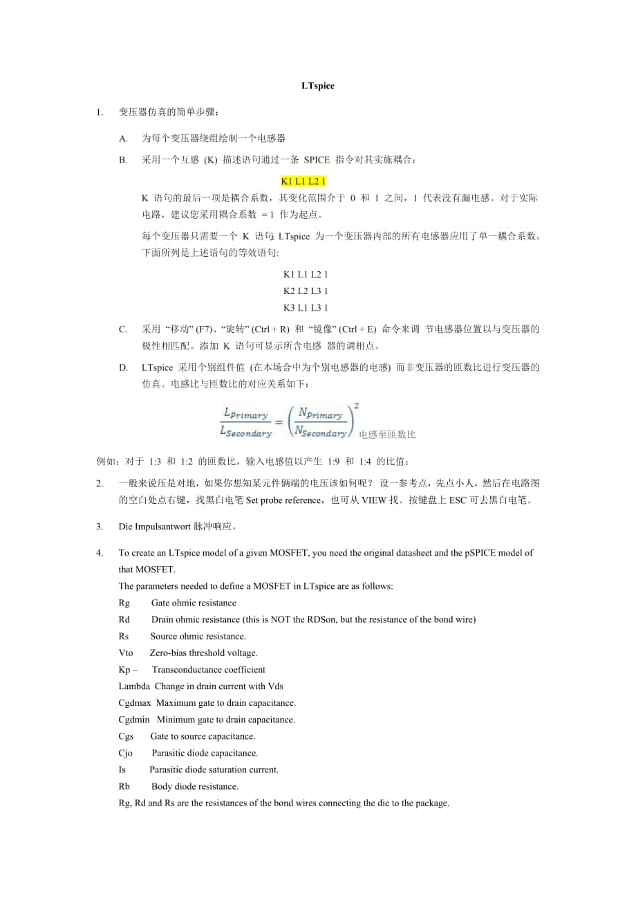
1、LTspice1. 变压器仿真的简单步骤:A. 为每个变压器绕组绘制一个电感器B. 采用一个互感 (K) 描述语句通过一条 SPICE 指令对其实施耦合: K1 L1 L2 1K 语句的最后一项是耦合系数,其变化范围介于 0 和 1 之间,1 代表没有漏电感。对于实际电路,建议您采用耦合系数 = 1 作为起点。每个变压器只需要一个 K 语句;LTspice 为一个变压器内部的所有电感器应用了单一耦合系数。下面所列是上述语句的等效语句: K1 L1 L2 1K2 L2 L3 1K3 L1 L3 1C. 采用 “移动” (F7)、“旋转” (Ctrl + R) 和 “镜像” (Ctrl + E)
2、命令来调 节电感器位置以与变压器的极性相匹配。添加 K 语句可显示所含电感 器的调相点。D. LTspice 采用个别组件值 (在本场合中为个别电感器的电感) 而非变压器的匝数比进行变压器的仿真。电感比与匝数比的对应关系如下:电感至匝数比例如:对于 1:3 和 1:2 的匝数比,输入电感值以产生 1:9 和 1:4 的比值:2. 一般来说压是对地,如果你想知某元件俩端的电压该如何呢?设一参考点,先点小人,然后在电路图的空白处点右键,找黑白电笔Setprobereference,也可从VIEW找。按键盘上ESC可去黑白电笔。3. DieImpulsantwort脉冲响应。4. To create
3、 an LTspice model of a given MOSFET, you need the original datasheet and the pSPICE model of that MOSFET.The parameters needed to define a MOSFET in LTspice are as follows:Rg Gate ohmic resistanceRd Drain ohmic resistance (this is NOT the RDSon, but the resistance of the bond wire)Rs Source ohmic re
4、sistance.Vto Zero-bias threshold voltage.Kp Transconductance coefficientLambda Change in drain current with VdsCgdmax Maximum gate to drain capacitance.Cgdmin Minimum gate to drain capacitance.Cgs Gate to source capacitance.Cjo Parasitic diode capacitance.Is Parasitic diode saturation current.Rb Bod
5、y diode resistance.Rg, Rd and Rs are the resistances of the bond wires connecting the die to the package.Vto is the turn on voltage of the MOSFET.Kp is the transconductance of the MOSFET. This determines the drain current that flows for a given gate source voltage.Lambda is the change in drain curre
6、nt with drain source voltage and is used with Kp to determine the RDSon.Cgdmax and Cgdmin are the minimum and maximum values of the gate drain capacitance and are normally graphed in the MOSFET datasheet as Crss. The capacitance of a capacitor is inversely proportional to the distance between its pl
7、ates. When the MOSFET is turned on, distance between the gate and the conducting channel of the drain is equal to the thickness of the insulating gate oxide layer (which is small) so the gate drain capacitance is high. When the MOSFET is turned off, the gate drain region is large, making the gate dr
8、ain capacitance low. This can be seen on the plot of Crss.Cgs is the gate source capacitance. Although it changes slightly with gate source voltage, LTspice assumes it is constant.Is is the parasitic body diode saturation current.Rb is the series resistance of the body diode.The Fairchild FDS6680A M
9、OSFET is defined in LTspice by the line.model FDS6680A VDMOS(Rg=3 Rd=5m Rs=1m Vto=2.2 Kp=63 Cgdmax=2n Cgdmin=1n Cgs=1.9n Cjo=1n Is=2.3p Rb=6m mfg=Fairchild Vds=30 Ron=15m Qg=27n)Note: the characteristics Vds, Ron and Qg are actually ignored by LTspice. These are only added to aid the user to compare
10、 MOSFETs.Therefore an example template MOSFET model is.model XXXX VDMOS(Rg= Rd=5 Rs=1 Vto= Kp= Cgdmax= Cgdmin= Cgs= Cjo= Is= Rb= )We are now going to construct a MOSFET model for the SUM75N06 and SUM110N04 low ON resistance MOSFETs from Vishay.model SUM75N06-09L VDMOS(Rg=1.5 Rd=0m Rs=25m Vto=2.0 Kp=
11、75 Cgdmax=1.2n Cgdmin=150p Cgs=2n Cjo=1.2n Is=1p Rb=0).model SUM110N04 VDMOS(Rg=1.5 Rd=0m Rs=0.86m Vto=1.85 Kp=180 Cgdmax=3n Cgdmin=900p Cgs=14.5n Cjo=4.9n Is=33.4p Rb=0)The SPICE models can then be testing using these test jigs:RDSon test jig为了测试MOSFET的RDSON,在 LTspice中导入测试电路。 Check the datasheet to
12、 see how the RDSOn has been tested. It will be characterised with a certain gate-source voltage and a certain drain current.Run the simulation. Probe the drain voltage. Probe the drain current. Edit the Drain current icon to readV(drain)/Id(M1). This changes one of the axes to read ON resistance. Yo
13、u may have to change the parameter Kp slightly to match the datasheet performance.Switching Time Test JigTo test the switching time of the MOSFET import the model into the LTspice test circuit. Check the datasheet to see how the switching times have been tested. They will be characterised with a cer
14、tain gate drive voltage, gate drive resistance and drain voltage and the response time will be characterised when the drain current ramps to a certain level.Run the simulation. Probe the gate voltage. Probe the drain current. Zoom in on the rising edge of the gate/drain waveforms. Left click on the
15、Drain current axis and rescale the axis to measure slightly over the current desired drain current. The timings can now be measured. Rise time is normally measured over 10% to 90% of the desired voltage swing. You may have to change the model capacitances slightly to meet datasheet performance.5. de
16、lete copy move component without wires attached move components with wires attached undoshift redo rotates component (once it has been selected using ) mirrors component (once it has been selected using )按住ALT键,左点击线,绘制该线上的电流波形。按住ALT键,左点击元件,在组件中显示瞬时功率。6. LTspice Tutorial 3: 生成效率报告为了生成效率报告,选择 Simulate
17、 - Edit Simulation cmd - mulating if steady state is detected. 返回到仿真界面,点击View - Efficiency Report - Show on Schematic. 效率报告就会显示在原理图上。(注意: 当只有一个电压源(被认为是输入),和或者一个电流源或者负载称为Rload(假定为负载),才能生成效率报告。)7. LTspice Tutorial 3: 使用数学函数来计算效率There is no reason why you cannot use the maths functions in LTspice to ex
18、amine efficiency and indeed this is an effective way of measuring the efficiency of a multi output system.8. 想要知道电路中有哪些寄生参数,可以按+H,原理图中会以高亮的形式显示哪些元件有寄生参数,点击取消。9. 如何将第三方模型导入LTspice下载SPICE模型,保存到所要仿真的电路的同一路径里;点击SPICE directive,添加以下SPICE 指令.include DI_BAT54.txt,打开SPICE(.txt)模型(in this case it is DI_BAT54
19、),注意模型的名称,按右键单击肖特基二极管符号和文本DI_BAT54粘贴到Value字段,如图1所示。10. 结温终端(Tj)可以用于读取结温或固定结温,这个终端可以浮动;壳温终端(Tc)必须连接到一个电压源或散热器RC网络,该终端不能浮动。11. n沟道mosfet安全工作区(SOA)行为建模打开SOAtherm-NMOS Example,启动原理图,运行这一仿真,它通过四个步骤加载不同条件下的输出:1,10,50,100按F2并选择SOAtherm-NMOS符号。把SOAtherm-NMOS NMOS的符号放到示意图中,使用CTRL+R旋转符号。SOAtherm-NMOS符号作为覆盖,NM
20、OS符号不应该被删除。将MOSFET符号放好之后,额外的电线应该自动删除。如果电线没有自动删除, 手动按下F5,选中,删除它们。打开SOAtherm-NMOS Tutorial 1。右键单击(或左键双击)SOAtherm-NMOS符号,出现SOAtherm-NMOS符号属性对话框,如下图所示。右键单击SpiceModel,在下拉菜单中选择SOAtherm-NMOS模型,本例选择PSMN4R8100BSE。如果使用的是Mac版本的LTspice,可以左击使字段可编辑,将MOSFET的名字直接粘贴到SpiceModel字段。然后添加Tj-FET和Tc-FET结点,分别与SOAtherm-NMOS
21、符号的Tj 和Tc 引脚相连(F3连线,F4插入结点标号(label net)。运行仿真,绘制Tj-FET结点电压,该电压表示结温(junction temperature,单位C),Tj-FET温度达到了132C,而起始温度为85C的原因是该符号的环境温度默认为85C。右键单击符号使Tambient Tambient从85C变为70C。打开SOAtherm-NMOS Tutorial 2。运行,会发现现在的最高结温Tj-FET是123C。根据datasheet,PSMN4R8100BSE MOSFET允许的最大结温为175C(大多数mosfet的最大结温150C或175C)。该仿真表明,由于最大结温小于175C,所以满足SOA极限,最坏的装载情况导致50C结温升。在SOAtherm符号的属性框添加RthetaJA =10,打开SOAtherm-NMOS Tutorial 3。PWL线性分段电源http:/www.simonbramble.co.uk/lt_spice/ltspice_lt_spice_tutorial_5.htm
- 温馨提示:
1: 本站所有资源如无特殊说明,都需要本地电脑安装OFFICE2007和PDF阅读器。图纸软件为CAD,CAXA,PROE,UG,SolidWorks等.压缩文件请下载最新的WinRAR软件解压。
2: 本站的文档不包含任何第三方提供的附件图纸等,如果需要附件,请联系上传者。文件的所有权益归上传用户所有。
3.本站RAR压缩包中若带图纸,网页内容里面会有图纸预览,若没有图纸预览就没有图纸。
4. 未经权益所有人同意不得将文件中的内容挪作商业或盈利用途。
5. 装配图网仅提供信息存储空间,仅对用户上传内容的表现方式做保护处理,对用户上传分享的文档内容本身不做任何修改或编辑,并不能对任何下载内容负责。
6. 下载文件中如有侵权或不适当内容,请与我们联系,我们立即纠正。
7. 本站不保证下载资源的准确性、安全性和完整性, 同时也不承担用户因使用这些下载资源对自己和他人造成任何形式的伤害或损失。
