 外文翻译--太阳能跟踪系统更有效率地运用的太阳能电池板(共20页)
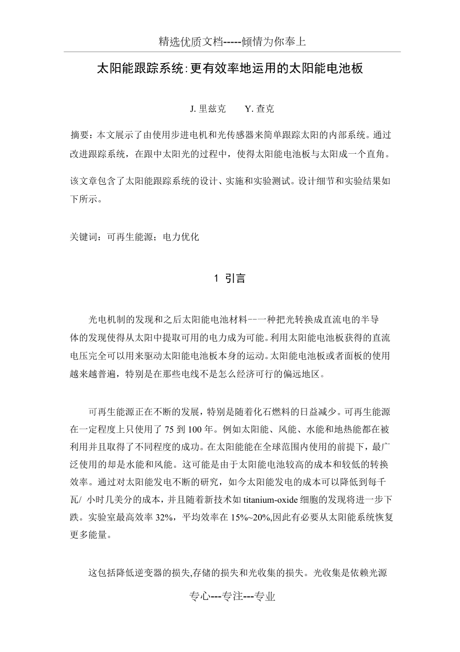

《外文翻译--太阳能跟踪系统更有效率地运用的太阳能电池板(共20页)》由会员分享,可在线阅读,更多相关《外文翻译--太阳能跟踪系统更有效率地运用的太阳能电池板(共20页)(20页珍藏版)》请在装配图网上搜索。
1、精选优质文档-倾情为你奉上太阳能跟踪系统:更有效率地运用的太阳能电池板J.里兹克Y.查克 摘要:本文展示了由使用步进电机和光传感器来简单跟踪太阳的内部系统。通过 改进跟踪系统,在跟中太阳光的过程中,使得太阳能电池板与太阳成一个直角。该文章包含了太阳能跟踪系统的设计、实施和实验测试。设计细节和实验结果如 下所示。关键词:可再生能源;电力优化1 引言光电机制的发现和之后太阳能电池材料-一种把光转换成直流电的半导 体的发现使得从太阳中提取可用的电力成为可能。利用太阳能电池板获得的直流 电压完全可以用来驱动太阳能电池板本身的运动。太阳能电池板或者面板的使用 越来越普遍,特别是在那些电线不是怎么经济可行
2、的偏远地区。可再生能源正在不断的发展,特别是随着化石燃料的日益减少。可再生能源 在一定程度上只使用了75到100年。例如太阳能、风能、水能和地热能都在被利用并且取得了不同程度的成功。在太阳能能在全球范围内使用的前提下,最广泛使用的却是水能和风能。这可能是由于太阳能电池较高的成本和较低的转换效率。通过对太阳能发电不断的研究,如今太阳能发电的成本可以降低到每千瓦/ 小时几美分的成本,并且随着新技术如 titanium-oxide 细胞的发现将进一步下跌。实验室最高效率32%,平均效率在15%20%,因此有必要从太阳能系统恢复更多能量。这包括降低逆变器的损失,存储的损失和光收集的损失。光收集是依赖光
3、源 的入射角(即太阳)与太阳能电池板的角度,角度越接近垂直、获得的太阳能越大。 如果一个平坦的太阳能板被安装在水平地面,很明显,在漫长的一天中阳光会有一 个入射角接近90。在这样的一个角度下,电池聚集光线的能力实质上是零,从而没 有输出。到正午的过程中,入射角越来越接近0,从而电能收集稳定增强,直到 太阳与电池板完全垂直,转化率才达到最大。就在这一天继续向黄昏走去时,相反的事情发生了,随着角度的增大,转化效 率向最小值迈进。专心-专注-专业从这一背景下,我们看到需要面板维持最大功率输出,必须使入射角尽可能 的接近0。通过倾斜太阳能板不断面对太阳,这样就可以实现上面那个要求。感 觉和跟踪太阳位置
4、的过程被称为太阳能跟踪。为了更有效地跟随太阳,实时跟踪 记录是必要的,因此操作中不需要额外的数据 。2 传感元件和信号处理许多不同的方法已经被提出并且用来跟踪太阳的位置。最简单的是使用一个 LDR用来检测在电阻表面的光强度变化的感光电阻。其他的方法,如 Jeff Damm 公布在“Home Power”的论文所说,把覆盖有一个小盘子的俩片光敏传感 器用来遮挡太阳光,如图1所示.图1 跟踪太阳光的方法当早晨来临时,该设备在昨天结束运动的位子如图一状态 A 所示;左光敏晶体 管是打开的,产生一个信号使得电机连续转动,直到板上的阴影返回到状态 B; 随着时间的慢慢变化,不久之后达到状态 C,这样就打
5、开了右边的光敏晶体管。 接着电机转动,直到再次达到 B 状态,并循环下去,直到一天结束,或直至达 到最小可探测光水平。像这样的设计存在一个问题,一旦光电晶体管被设置在偏置条件下,会降 低它的敏感性。这实际上是因为太阳能电池本身被选为传感装置。他们提供了一 个优良的光强度检测机制 - 因为它们对不同的光线有不同的敏感度和能够提供 接近线性的电压状况,可以用来确定目前的太阳偏角或角度。因此一个简单的带 有两个方向相反的太阳能电池板的三角形模型被制造出来,如图2所示:图2太阳能参考单元图3太阳能电池静止位置就如在图3中所看到的情况一样,太阳能电池板在其静止位置时,虽然入射 角并不是90,但是也同时接
6、收等量太阳光。图4中可以看出,当太阳在天空移动时,假设该太阳能电池板没有还没有移 动,由于光的入射角得变化,电池板的一边会比另一边获得更多的太阳光。所以 这一边所获得能量会高于另一边,因此电池板之间将会产生一个电压差。这种现 象会使得在每一个单元中产生可检测的信号,他可以通过合适的电路进行处理。图4太阳能电池在特殊角度向太阳3 太阳能跟踪装置样本该装置该装置撤消修改该装置的最新样品由涉及耦合电路的电机和安装支架组成。整机如图5所示。 它有一个安装在法兰上的多晶硅组成的 Sola rex 9W 太阳能电池板。对该样品进行了两个简单的测试。第一个测试将面板从设备上拿下来,并且 放置在一个平面上,连
7、接上一个匹配面板评级的输出为9W 的负载。12V9W 对应 0.75A 的电流,所以由欧姆定律计算负载电阻为16。1550W 被发现最接近该数值,所以连接到面板上。跟踪设备仍然需要动力,因此有一个与太阳能电池板相连接,并且通过充电器供给12V 电压的电池。通过两个单独的电表分别检测电路两端的电压和电流,由此在每一个晴朗的 日子里记录下数据,并且制作成一个 Excel 表格。在一个万里无云的天气中,每 隔一段时间采集一组数据。数据所生成的 Excel 表格如图6所示。通过在 Excel 中进行相应的计算,计算一个百分比的增加和平均增幅是完全 可能的。可以发现,在这样的天气条件下,12个小时时间里
8、,面板平均提供了整体的39%的输出,即3.51W。相比之下,能够跟踪的太阳能电池板同一时间内实现了整体的71的输出,即6.3W。特别是在早上和旁晚,能够跟踪的太阳能电池板的功率与面板相比增加了400%。简单的使太阳能电池板与太阳光尽可能的保持垂直,就能使功率平均增加30%。 图6功率测试实验结果 图5 太阳能跟踪装置为了确保能量不被浪费,设备本身也监测了电源本身的电流。设备在停止运 动时,一个电流表与电池一起串联在电路中。在12V 的总电压下,电流测量值仅 仅4mA,相当于在没有负载时功耗48MW。一个太阳能跟踪器被提出,设计和制造。它最终的设计是成功的,在同一面板条 件下,固定面板只能收集3
9、9%的总输出相比,而跟踪装置可以达到70%的总输出。而真正的价值是:这表明可以显著降低系统的整体成本,并且可以通过耦合太阳 能跟踪装置的太阳能电池板收集更多的能量。通过相同的太阳能电池板,提取更多的能量,收集一瓦能量的成本也大大降低。与以前固定的太阳能电池板相比, 从而使得此类太阳能发电更具有成本效益。太阳能跟踪系统的高成本已经成为现实,使得整体提高太阳能电池的效率更加艰 难。许多商业单位制造一个跟踪装置并且带有相当质量的面板需要花费2000多美元。在本论文中提出的设备由于其结构简单,电机的高扭矩能力,能够支持一个至少8千克的负载一个75W 的太阳能电池板的平均重量。并且用于此设备的零件成本也
10、非常低,包括所有的电子元件和太阳能电池板,再加上一些废旧材料的花费,成本也只花费30美元。除了9W 的太阳能电池板,其他的均来自于各种废旧物品。驱动装置是从旧的安全摄像头上拆下来的,步进电机来自于旧的打印机。然而,如果所有这些部件都必须购买,成本将预计不超过100美元。一个单轴跟踪系统,例如它提高了固定太阳能电池板的动力,但是双轴跟踪系统将提供更多的能量。这可能是一个进一步发展的主题。太阳能跟踪时迄今为止提高住宅和商业用户使用太阳能发电系统的整体效率的最简单方法。通过本篇文中的简单设计,个人也可以用来制造简单的跟踪设备。4总结太阳能跟踪系统的设计采用通过小型太阳能电池去自我调节的光传感器的 新
11、方法,通过检测输出电压,改变太阳能电板与太阳之间的相对角度。通过使用 这种方法,太阳能跟踪器能够成功的使太阳光和太阳能电池板之间保持垂直。该 设备与固定的太阳能面板相比,多获得超过30%的太阳能。参考文献1 Fahrenburch, A. and Bube, R. 1983, Fundamentals of solar cells, Academic Press, New York.2 Partain, L.D. 1995, Sollar Cells an d their applications, John Wiley & Sons. New York.3 E Weise, R Klockn
12、er, R Kniel, Ma Sheng Hong, Qin Jian Ping, “Remote Power Supply Using Wind and Sola r energy a Sino-German Technical Cooperation Project”, Beijing International Conference on Wind Energy, Beijing, 19954 Wichert B, Lawrance W, Friese T, First Experiences with a Novel Predictive Control Strategy for P
13、V-Diesel Hybrid Energy Systems, Solar995 Duryea S, Syed I, Lawrence W, An Automated Battery Management System for Photovoltaic Systems, International Journal of Renewable Energy Engineering, Vol 1, No 2, Aug 19996 Twidell J, Weir J, Renewable Energy Systems, Chapman and Hall, 19947 Centre for Resour
14、ces and Environmental Studies, ANU, Sustainable Energy Systems Pathways for Australian Energy Reforms, Cambridge University Press, 19948 Damm, J. Issue #17, June/July 1990. An active solar tracking system, HomeBrew Magazine.Solar Tracking System: More Efficient Use of Solar PanelsJ. Rizk , Y. Chaiko
15、Abstract: This paper shows the potential system benefits of simple tracking solar system using a stepper motor and light sensor. This method is increasing power collection efficiency by developing a device that tracks the sun to keep the panel at a right angle to its rays. A solar tracking system is
16、 designed, implemented and experimentally tested. The design de tails and the experimental results are shown.Keywords :Renewable Energy, Power Optimization.I. INTRODUCTIONExtrecting useable electricity from the sun was made possible by the discovery of the photoelectric mechanism and subsequent deve
17、lopment of the solar cell a semi-conductive material that converts visible light into a direct current. By using solar arrays, a series of solar cells electrically connected, a DC voltage is generated which can be physically used on a load. Solar arrays or panels are being used increasingly as effic
18、iencies reach higher levels, and are especially popular in remote areas where placement of electricity lines is not economically viable. This alternative power source is continuously achieving greater popularity especially since the realisation of fossil fuels shortcomings. Renewable energy in the f
19、orm of electricity has been in use to some degree as long as 75 or 100 years ago. Sources such as Solar, Wind, Hydro and Geo-thermal have all been utilised with varying levels of success. The most widely used are hydro and wind power, with solar power being moderately used worldwide. This can be att
20、ributed to the relatively high cost of solar cells and their low conversion efficiency. Solar power is being heavily researched, and solar energy costs have now reached within a few cents per kW/h of other forms of electricity generation, and will drop further with new technologies such as titanium-
21、oxide cells. With a peak laboratory efficiency of 32% and average efficiency of 15-20%, it is necessary to recover as much energy as possible from a solar powersystem.This includes reducing inverter losses, storage losses, and light gathering losses. Light gathering is dependent on the angle of inci
22、dence of the light source providing power (i.e. the sun) to the solar cells surface, and the closer to perpendicular, the greater the power 1-7. If a flat solar panel is mounted on level ground, it is obvious that over the course of the day the sunlight will have an angle of incidence close to 90 in
23、 the morning and the evening. At such an angle, the light gathering ability of the cell is essentially zero, resulting in no output. As the day progresses to midday, the angle of incidence approaches 0 , causing an steady increase in power until at the point where the light incident on the panel is
24、completely perpendicular, and maximum power is achieved.As the day continues toward dusk, the reverse happens, and the increasing angle causes the power to decrease again toward minimum again.From this background, we see the need to maintain the maximum power output from the panel by maintaining an
25、angle of incidence as close to 0 as possible. By tilting the solar panel to continuously face the sun, this can be achieved. This process of sensing and following the position of the sun is known as Solar Tracking. It was resolved that real-time tracking would be necessary to follow the sun effectiv
26、ely, so that no external data would be required in operation.II. THE SENSINGELEMENT ANDS IGNAL PROCESSINGMany different methods have been proposed and used to track the position of the sun. The simplest of all uses an LDR a Light Dependent Resistor to detect light intensity changes on the surface of
27、 the resistor. Other methods, such as that published by Jeff Damm in Home Power 8, use two phototransistors covered with a small plate to act as a shield to sunlight, as shown in Fig. 1.Fig. 1 Alternative solar tracking methodWhen morning arrives, the tracker is in state A from the previous day. The
28、 left phototransistor is turned on, causing a signal to turn the motor continuously until the shadow from the plate returns the tracker to state B. As the day slowly progresses, state C is reached shortly, turning on the right phototransistor. The motor turns until state B is reached again, and the
29、cycle continues until the end of the day, or until the minimum detectable light level is reached. The problem with a design like this is that phototransistors have a narrow range of sensitivity, once they have been set up in a circuit under set bias conditions. It was because of this fact that solar
30、 cells themselves were chosen to be the sensing devices. They provide an excellent mechanism in light intensity detection because they are sensitive to varying light and provide a near-linear voltage range that can be used to an advantage in determining the present declination or angle to the sun. A
31、s a result, a simple triangular set-up was proposed, with the two solar cells facing opposite directions, as shown in Fig. 2.In its rest position, the solar cells both receive an equal amount of sunlight, as the angle of incidence, although not 90 , is equal in both cases as seen in Fig. 3.Fig. 2Set
32、-up of solar reference cellsFig. 3Solar reference cells at rest positionFig. 4 Solar reference cells at a significant angle to the sunIt can be seen in Fig. 4 that as the sun moves in the sky, assuming that the solar tracker has not yet moved, the angle of incidence of light to the reference panels
33、will cause more light to fall on one cell than the other.This will obviously cause a voltage difference, where the cell that is facing the sun will have higher potential than the other. This phenomenon will result in a detectable signal at each cell, which can be processed by a suitable circuit.III.
34、APROTOTYPESOLARTRACKERThe final stage involved coupling the circuitry to the motor and mounting it onto the bracket The final product is seen complete in Fig. 5. It has a Solarex 9W solar array made of polycrystalline silicon mounted on the flanges, which was borrowed from the tech officers.Quite si
35、mply having two test subjects carried out testing. The first scenario involved removing the panel from the tracker and laying it in a flat orientation. The output was connected to a load that would dissipate 9W that would match the panelsrating. 9W at 12V corresponds to a current of 0.75A, so by Ohm
36、 s law; a loadresistance was calculated as being 16 . A 15 50W resistor was the closest value found and was connected to the panel. The tracking device still requires power, but a 12V battery that is connected in a charging arrangement with the solar panel supplies it. The voltage across and current
37、 through the load was monitored using two separatemultimeters, and was recorded every half-hour on a clear day into an Ex cel spreadsheet. The readings were taken on a span of days that possessed similar conditions including no cloud cover. The readings are shown below in a graph generated by Excel
38、in Fig. 6.It is possible to calculate a percentage increase and an average increase by writing the appropriate calculations in excel. It was found that in this case, the fixed panel provided an average of 39% of its 9W, or 3.51W, calculated over a 12-hour period. By contrast, the tracked solar panel
39、 achieved an overall 71% output, or 6.3W over the same time frame. At the earlier and later hours, the power increase over the fixed panel reached up to 400%. This amounts to an average 30% increase in power simply by maintaining the solar panel as perpendicular as possible to the sun.To ensure that
40、 power was not being wasted, the device itself was also monitored for current drawn to power itself. When the device was at rest, an ammeter was placed in series with the battery. The total current at 12V was measured as only 4mA, which corresponded to a power dissipation of 48mW under no load.Fig.
41、5 A prototype solar trackerFig. 6 Experimental results of power increase fortracked panelIV.CONCLUSIONA solar tracker is designed employing the new principle of using small solar cells to function as self-adjusting light sensors, providing a variable indication of their relative angle to the sun by
42、detecting their voltage output. By using this method, the solar tracker was successful in maintaining a solar array at a sufficiently perpendicular angle to the sun. The power increase gained over a fixed horizontal array was in excess of 30%.REFERENCES1 Fahrenburch, A. and Bube, R. 1983, Fundamenta
43、ls of solar cells, Academic Press, New York.2 Partain, L.D. 1995, Sollar Cells an d their applications, John Wiley & Sons. New York.3 E Weise, R Klockner, R Kniel, Ma Sheng Hong, Qin Jian Ping, “Remote Power Supply Using Wind and Sola r energy a Sino-German Technical Cooperation Project”, Beijing In
44、ternational Conference on Wind Energy, Beijing, 19954 Wichert B, Lawrance W, Friese T, First Experiences with a Novel Predictive Control Strategy for PV-Diesel Hybrid Energy Systems, Solar995 Duryea S, Syed I, Lawrence W, An Automated Battery Management System for Photovoltaic Systems, International
45、 Journal of Renewable Energy Engineering,Vol 1, No 2, Aug 19996 Twidell J, Weir J, Renewable Energy Systems, Chapman and Hall, 19947 Centre for Resources and Environmental Studies, ANU, Sustainable Energy Systems Pathways for Australian Energy Reforms, Cambridge University Press, 19948 Damm, J. Issue #17, June/July 1990. An active solar tracking system, HomeBrew Magazine.
- 温馨提示:
1: 本站所有资源如无特殊说明,都需要本地电脑安装OFFICE2007和PDF阅读器。图纸软件为CAD,CAXA,PROE,UG,SolidWorks等.压缩文件请下载最新的WinRAR软件解压。
2: 本站的文档不包含任何第三方提供的附件图纸等,如果需要附件,请联系上传者。文件的所有权益归上传用户所有。
3.本站RAR压缩包中若带图纸,网页内容里面会有图纸预览,若没有图纸预览就没有图纸。
4. 未经权益所有人同意不得将文件中的内容挪作商业或盈利用途。
5. 装配图网仅提供信息存储空间,仅对用户上传内容的表现方式做保护处理,对用户上传分享的文档内容本身不做任何修改或编辑,并不能对任何下载内容负责。
6. 下载文件中如有侵权或不适当内容,请与我们联系,我们立即纠正。
7. 本站不保证下载资源的准确性、安全性和完整性, 同时也不承担用户因使用这些下载资源对自己和他人造成任何形式的伤害或损失。
