 机器人摄像头030ov7910 18p

《机器人摄像头030ov7910 18p》由会员分享,可在线阅读,更多相关《机器人摄像头030ov7910 18p(18页珍藏版)》请在装配图网上搜索。
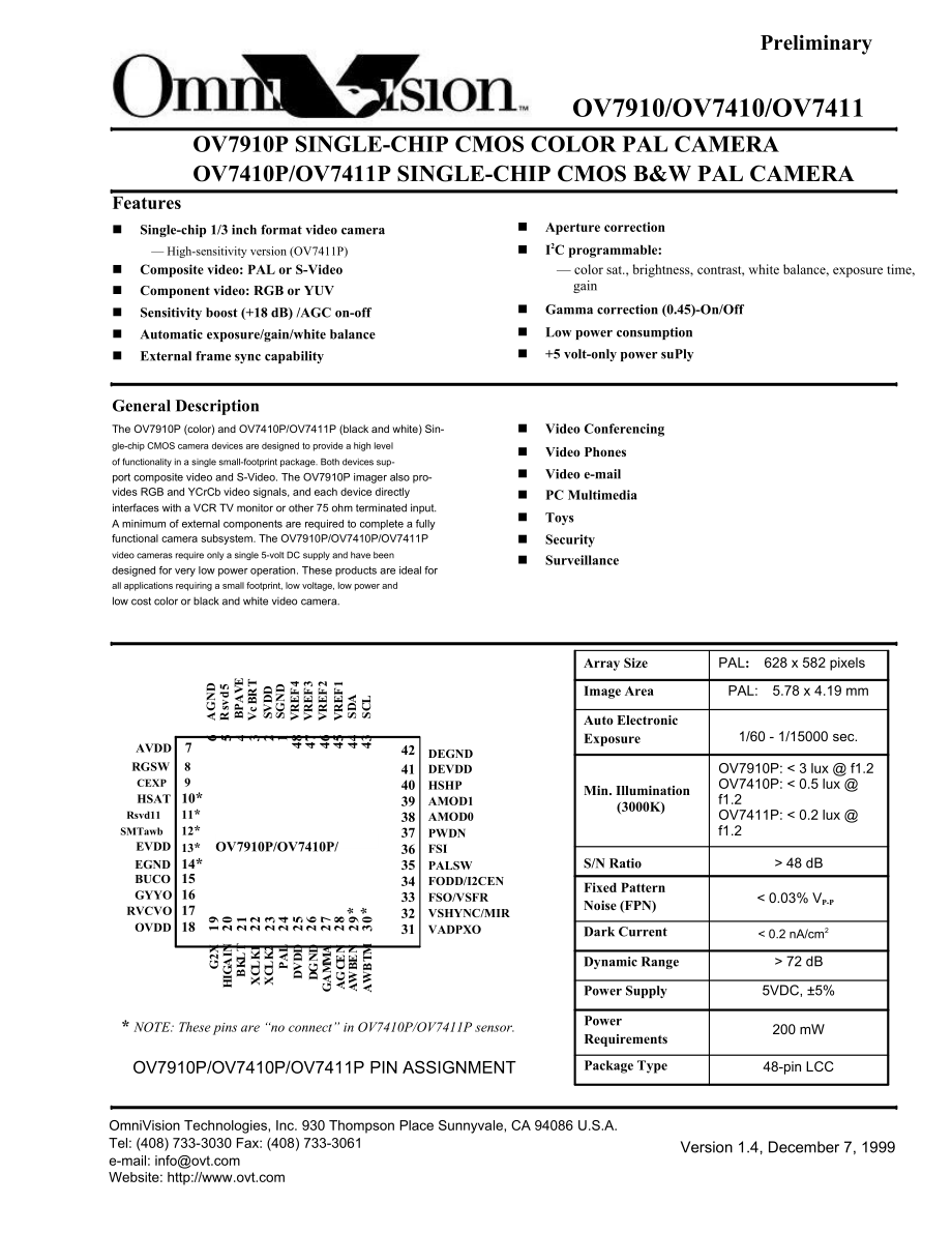
1、FeaturesPreliminaryOV7910/OV7410/OV7411OV7910P SINGLE-CHIP CMOS COLOR PAL CAMERAOV7410P/OV7411P SINGLE-CHIP CMOS B&W PAL CAMERAnSingle-chip 1/3 inch format video camera High-sensitivity version (OV7411P)nComposite video: PAL or S-VideonComponent video: RGB or YUVnSensitivity boost (+18 dB) /AGC on-o
2、ffnAutomatic exposure/gain/white balancenExternal frame sync capabilityGeneral DescriptionThe OV7910P (color) and OV7410P/OV7411P (black and white) Sin-gle-chip CMOS camera devices are designed to provide a high levelof functionality in a single small-footprint package. Both devices sup-port composi
3、te video and S-Video. The OV7910P imager also pro-vides RGB and YCrCb video signals, and each device directlyinterfaces with a VCR TV monitor or other 75 ohm terminated input.A minimum of external components are required to complete a fullyfunctional camera subsystem. The OV7910P/OV7410P/OV7411Pvide
4、o cameras require only a single 5-volt DC supply and have beendesigned for very low power operation. These products are ideal forall applications requiring a small footprint, low voltage, low power andlow cost color or black and white video camera.nAperture correctionnI2C programmable: color sat., b
5、rightness, contrast, white balance, exposure time,gainnGamma correction (0.45)-On/OffnLow power consumptionn+5 volt-only power suPlynVideo ConferencingnVideo PhonesnVideo e-mailnPC MultimedianToysnSecuritynSurveillance Array SizePAL:628 x 582 pixelsImage AreaPAL:5.78 x 4.19 mmAuto ElectronicAVDD 7RG
6、SW 8CEXP 9HSAT10*Rsvd1111*SMTawb12*424140393837DEGNDDEVDDHSHPAMOD1AMOD0PWDNExposureMin. Illumination(3000K)1/60 - 1/15000 sec.OV7910P: 3 lux f1.2OV7410P: 0.5 lux f1.2OV7411P: 48 dB 0.03% VP-P 72 dB5VDC, 5%* NOTE: These pins are “no connect” in OV7410P/OV7411P sensor.OV7910P/OV7410P/OV7411P PIN ASSIG
7、NMENTPowerRequirementsPackage Type200 mW48-pin LCCOmniVision Technologies, Inc. 930 Thompson Place Sunnyvale, CA 94086 U.S.A.Tel: (408) 733-3030 Fax: (408) 733-3061e-mail: infoWebsite: Version 1.4, December 7, 1999 A G N D R s v d 5 B P A V E V c B R T S V D D S G N D V R E F 4 V R E F 3 V R E F 1 S
8、 D A S C L G 2 X H IG A IN B K L T X C L K 1 X C L K 2 P A L D G N D G A M M A A G C E N D V D D A W B E N A W B T M V R E F 2 6 5 4 3 2 1 4 8 4 7 4 6 4 5 4 4 4 3 1 9 2 0 2 1 2 2 2 3 2 4 2 5 2 6 2 7 2 8 2 9 * 3 0 *OMNIVISION TECHNOLOGIES, Inc.OV7910P/OV7410P/OV7411PTable 1. Pin DescriptionPreliminar
9、ySINGLE IC CMOS COLOR & B/W PAL ANALOG CAMERAS(Pins designated with “*” are “no connect” in OV7410P/OV7411P sensor.)Pin No.NamePin TypeFunction/Description201020304050607080910*11*12*13*14*15SGNDSVDDVcBRTBPAVERsvd5AGNDAVDDRGSWCEXPHSATRsvd11SMTawbEVDDEGNDBUCOVinVin1.2VFunction(Default = 0)VrefVinVinF
10、unction(Default = 0)Function(Default = 0)Function(Default = 0)(N/C on OV7410P/OV7411P)N/CFunction(Default = 0)(N/C on OV7410P/OV7411P)Vin(N/C on OV7410P/OV7411P)Vin(N/C on OV7410P/OV7411P)OutputAnalog groundAnalog power (+5VDC)Image brightness adjustment. Default set by internal resistor (50K). Defa
11、ult may be changedby applying external bias to this pin.Internal 3-point average selection“0” - Use internal 3-point averaging“1” - Bypass internal 3-point averagingInternal referenceAnalog groundAnalog power (+5VDC)“Raw” data pixel selection“0” - select non- “raw” pixel data“1” - select “raw” pixel
12、 dataCentral exposure selection“0” - select normal mode“1” - select central exposure modeColor Saturation selection“0” - select normal color saturation“1” - select increase color saturation by 25%Note: This function is not available on OV7410P/OV7411P Image Sensor. This pin is “no con-nect”.Pin rese
13、rvedAutomatic White Balance (AWB) Smart mode selection“0” - Disable smart mode“1” - Enable smart mode. Count pixels which contain a luminance signal between 10-80% ofmax. value.Note: This function is not available on OV7410P/OV7411P Image Sensor. This pin is “no con-nect”.Analog power (+5VDC)Note: T
14、his function is not available on OV7410P/OV7411P Image Sensor. This pin is “no con-nect”.Analog groundNote: This function is not available on OV7410P/OV7411P Image Sensor. This pin is “no con-nect”.Video Output: Output format determined by pins 38 and 39 (AMOD1, AMOD0)AMOD1AMOD0Output ComponentForma
15、t00S-Video CO channelComposite01Blue componentRGB10Cb componentYUV or B/W11Blue componentRGBNote: Modes (AMOD1, AMOD0) = 00, 01, 11 are not available for OV7410P Image Sensor Version 1.4December 7, 1999OMNIVISION TECHNOLOGIES, Inc.OV7910P/OV7410P/OV7411PTable 1. Pin DescriptionPreliminarySINGLE IC C
16、MOS COLOR & B/W PAL ANALOG CAMERAS(Pins designated with “*” are “no connect” in OV7410P/OV7411P sensor.)Pin No.NamePin TypeFunction/Description1617181920212223242526272829*GYYORVCVOOVDDG2XHGAINBKLTXCLK1XCLK2PALDVDDDGNDGAMMAAGCENAWBENOutputOutputVinFunction(Default = 0)Function(Default = 0)Function(D
17、efault = 0)CLKCLKFunction(Default = 1)VinVinFunction(Default = 1)Function(Default = 1)Function(Default = 1)(N/C on OV7410P/OV7411P)Video Output: Output format determined by pins 38 and 39 (AMOD1, AMOD0)AMOD1AMOD0Output ComponentFormat00S-Video YO channelComposite01Green componentRGB10Y componentYUV
18、or B/W11Green componentRGBNote: Modes (AMOD1, AMOD0) = 00, 01, 11 are not available for OV7410P Image SensorVideo Output: Output format determined by pins 38 and 39 (AMOD1, AMOD0)AMOD1AMOD0Output ComponentFormat00CVBS signalComposite01Red componentRGB10Cr componentYUV or B/W11Red componentRGBNote: M
19、odes (AMOD1, AMOD0) = 00, 01, 11 are not available for OV7410P Image SensorAnalog power for video output (+5VDC)Automatic Gain Control (AGC) gain selection. Affects range selected by HGAIN (p20). SeeHGAIN below.“0” - select normal AGC gain (1X)“1” - select enhanced AGC gain (2X)Automatic Gain Contro
20、l (AGC) gain range selection“0” - select normal AGC range (1X 4X)“1” - select expanded AGC range (1X - 8X)HGAING2XAGC Range001X 4X012X 8X101X 8X112X 16XBacklight selection“0” - Disable backlight compensation“1” - Enable backlight compensationCrystal clock input. Frequency is 4 x Fsc to meet PAL subc
21、arrier standardsCrystal clock output (4 x Fsc for PAL = 17.73265 MHz)Digital powerDigital groundGAMMA selection“0” - Disable GAMMA correction“1” - Enable GAMMA correctionAutomatic Gain Control (AGC) selection“0” - Disable AGC“1” - Enable AGCAutomatic White Balance selection“0” - Disable AWB“1” - Ena
22、ble AWBNote: This function is not available on OV7410P/OV7411P Image Sensor. This pin is “no con-nect”.December 7, 1999 Version 1.43OMNIVISION TECHNOLOGIES, Inc.OV7910P/OV7410P/OV7411PTable 1. Pin DescriptionPreliminarySINGLE IC CMOS COLOR & B/W PAL ANALOG CAMERAS(Pins designated with “*” are “no co
23、nnect” in OV7410P/OV7411P sensor.)Pin No.NamePin TypeFunction/Description30*31AWBTMVAXPXOFunction(Default = 0)(N/C on OV7410P/OV7411P)OutputAutomatic White Balance speed selection“0” - Select normal AWB“1” - Select “fast” AWBNote: This function is not available on OV7410P/OV7411P Image Sensor. This
24、pin is “no con-nect”.Valid pixel detect output. CLK is asserted on this pin during active image period.32VHSYNC/MIROutput/Function(Default = 0)Vertical/horizontal sync output. Adding a pullup resistor on this pin enables mirror image33FSO/VSFROutput/Function(Default = 0)Vertical field/frame sync out
25、put, default to field sync. Adding a pullup resistor on this pin enablesframe sync.34FODD/I2CENOutput/Function(Default = 0)Even/Odd field flag. Adding a pullup resistor on this pin enables I2C control.43536373839404142434445464748PALSWFSIPWDNAMOD0AMOD1HSHPDEVDDDEGNZDSCLSDAVREF1VREF2VREF3VREF4OutputI
26、nputFunctionFunctionFunctionFunctionVinVinInput/OutputInput/OutputVrefVrefVrefVrefPAL switch clock outputField sync inputPower Down mode selection“0” - Disable power down mode“1” - Enable power down modeAMOD0 (w/AMOD1) selects output mode.Note: This function is not available on OV7410P/OV7411P Image
27、 Sensor. This pin is “no con-nect”.AMOD1 (w/AMOD0) selects output mode.Note: This function is not available on OV7410P/OV7411P Image Sensor. This pin is “no con-nect”.Sharpness level selection“0” - select normal sharpness“1” - select x2 sharpnessAnalog powerAnalog groundI2C controlI2C data/addressIn
28、ternal reference. Must be decoupled with 0.1 F capacitor to analog ground.Internal reference. Must be decoupled with 0.1 F capacitor to analog ground.Internal reference. Must be decoupled with 0.1 F capacitor to analog ground.Internal reference. Must be decoupled with 0.1 F capacitor to analog groun
29、d. Version 1.4December 7, 1999OMNIVISION TECHNOLOGIES, Inc.OV7910P/OV7410P/OV7411P1.Functional DescriptionPreliminarySINGLE IC CMOS COLOR & B/W PAL ANALOG CAMERAS(Note: All references to color functions apply only to OV7910P image sensor)1.1Video StandardsTwo TV standards are implemented and availab
30、le asoutput in the OV7910P/OV7410P/OV7411P imagingdevices: PAL (B). Table 2 below shows how to config-ure the standard of choice. Please noteTable 2. Standard Configurationthat the accuracy and stability of the crystal clock fre-quency is important to avoid unwanted color shift in TV/video systems.S
31、tandardPALPAL(pin 24)1Clock17.734475 MHzCommentsclock in = 4 x Fsc1.2Video FormatsTheOV7910P/OV7410P/OV7411Pimagesensorssupport a variety of formats including Composite(CVBS), S-Video (YO/CO), RGB components, YUVcomponents, and B/W. Composite and S-Video signalsare generated from the internal TV enc
32、oder and theRGB/YUV/BW outputs are generated from the colormatrix prior to entering the encoder.configuration for the OV7910P/OV7410P/OV7411Pimage sensors. Pins AMOD0/AMOD1 (pins 38 and 39)select composite and S-Video formats. In this configu-ration, RVCVO (pin 17) outputs CVBS, GYYO (pin 16)outputs
33、1.2.2RGBSetting AMOD0 = 1 (w/AMOD1 = x) selects the RGBformat. In this configuration, RVCVO outputs the1.2.3YUVSetting AMOD0=0 and AMOD1=1 configures theOV7910P/OV7410P/OV7411P sensors to operate inYUV or B/W mode. In this configuration, GYYO outputsthe Y component, RVCVO provides the Cr component,T
34、he image sensor utilizes the RG/BG Bayer patternsending raw pixel data through the color matrix, creat-ing RGB or YUV component signals. At the same time,YUV signals are also processed to generate both com-posite and S-Video signals. (Note: Color format config-uration is valid only for the OV7910P i
35、mage sensor)1.2.1Composite and S-VideoThe Composite/S-Video format is the power-up defaultthe YO component of the S-Video signal, and BUCO(pin 15) outputs the CO component. Table 3 belowsummarizes the formats available and the settingsrequired on the appropriate pins.Red component, GYYO outputs the
36、Green component,and BUCO provides the Blue component.and BUCO outputs the Cb component. On theOV7410P image sensor, only the GYYO (Y compo-nent) output is valid.December 7, 1999 Version 1.45OMNIVISION TECHNOLOGIES, Inc.OV7910P/OV7410P/OV7411PTable 3. Video Format SelectionPreliminarySINGLE IC CMOS C
37、OLOR & B/W PAL ANALOG CAMERASFormat TypeComposite + S-VideoRGB ComponentsYUV ComponentsBlack and WhiteRVCVO Output(pin 17)CVBSRedCrGYYO Output(pin 16)YOGreenYYBUCO Output(pin 15)COBlueCbPin SettingsAMOD0 = 0, AMOD1 = 0AMOD0 = 1, AMOD1 = xAMOD0 = 0, AMOD1 = 1AMOD0 = 0, AMOD1 = 1(Pins 15 & 17 are unde
38、fined on the OV7410P sen-sor)1.3Configuring the OV7910P/OV7410P/OV7411PImage Sensors for OperationThe OV7910P/OV7410P/OV7411P sensors have beendesigned for easy-of-use in many stand-alone applica-tions. Most of the on-chip functions are configurable byconnecting appropriate pins high (logic “1”) or
39、low(logic “0”) through a 10k Ohm resistor. The image sen-sor reads the input the pins at power up, which enablesuser-defined default configurations.The OV7910P/OV7410P/OV7411P imaging devicesalso contain an I2C interface for programmatic accesssensors will enable the I2C port for access.1.4White Bal
40、anceThe function of white balance in the OV7910P imagesensor is to adjust and calibrate the image devicessensitivity on the primary (RGB) colors to match thecolor cast of the light source. The Auto White Balance(AWB) can be enabled or disabled either through anexternal pin (AWBEN, pin 29) or through
41、 the I2C port. Ifable only through the I2C port. This function enablesthe user to define a “cooler” or “warmer” backgroundfor image capture.1.5Additional Picture ControlA number of functions/registers are available whichenable the user to configure OV7910P/OV7410P/OV7411P image capturing parameters.
42、 These func-tions include Automatic Gain Control (AGC), AGCGain, Automatic Exposure Control (AEC), GAMMA,to allregister functions (For further details on I2C, see Sec-tion 2. “I2C Bus” on page 11). By default, the I2C port isdisabled. To enable the I2C for controlling the sensors,a 10K Ohm pull-up r
43、esistor must be connected toFODD/I2CEN. With FODD/I2CEN pulled high atpower-up, the OV7910P/OV7410P/OV7411P imageAWB is enabled, the image sensors continuously per-form white balancing. A fast or slow mode of white bal-ancing may be user-selected (AWBTM, pin 30). FastAWB updates color every 2 fields
44、 while slowwhite balancing updates every 16 fields.By using the I2C port, the color temperature may befurther fine tuned to the requirement of the application.Note that the “blue” (Blue and Blue bias registers) and“red” (Red and Red bias registers) bias control is avail-and Backlight control.HGAIN (
45、pin 20) may be used to set the range of AGCGain. A “0” on HGAIN sets AGC Gain range for 1X 4X, while a “1” sets the range for 1X 8X. G2X (pin19) can then be used to enhance the AGC gain range.A “0” on G2X sets AGC gain at normal. A “1” enhancesthe AGC gain by 2 (Refer to Table 1, “Pin Description,”o
46、n page 2, pins 19 and 20 for further details). Thisfunction may be configured through the I2C port, as6 Version 1.4December 7, 1999OMNIVISION TECHNOLOGIES, Inc.OV7910P/OV7410P/OV7411PPreliminarySINGLE IC CMOS COLOR & B/W PAL ANALOG CAMERASwell. GAMMA (pin 27) can be used to set the GAMMAcorrection.
47、BKLT (pin 21) controls how the OV7910P/OV7410P/OV7411P image sensors manage backlightconditions. These functions may also be controlledthrough the I2C interface.At power up, AGC and AEC are enabled. AGC can bedisabled at power up by configuring the AGCEN pin(pin 28) as required. AEC cannot be enable
48、d/disabledexternally and must be reprogrammed through the I2Cport.1.6Other Image Sensor Control FunctionsAdditional programmable functions for the OV7910P/OV7410P/OV7411P image sensors include sharpnessadjustment, brightness level fine tune, color saturationadjustment, mirror image control, and powe
49、r down. Allof these functions (except power down) can be config-ured either by an external pin or through the I2C inter-face.December 7, 1999 Version 1.47OMNIVISION TECHNOLOGIES, Inc.OV7910P/OV7410P/OV7411PSpecificationsPreliminarySINGLE IC CMOS COLOR & B/W PAL ANALOG CAMERASTable 4. Electrical para
50、meters (0oC to 70 oC, all voltages referenced to GND)SymbolDescriptionsMaxTypSupplyMinUnitsVDDIDDI2Cfscltftidlethdstat stpstdstdhSupply voltage (VDD, DVDD)Supply Current in VDDsSCL clock frequencySDA fall timeBus idle timeSTART hold timeSTOP set up timeSDA set up timeSDA hold time5.2540400300-5.0-4.
51、75-20 + 0.1Csda1.30.60.61000VmAkHznsusususususClock input / Crystal OscillatorfoscResonator frequencyLoad capacitorParallel resistanceRise/fall time for external clock inputDuty cycle for external clock inputMisc. timing10-60-101M520-40MHzpFWns%tSYNCtPUtPDtPZExternal FSI cycle timeChip power up time
52、Power up delay timePower up low-z delay-100-2-101000-frameususnsVTO analog video output parametersVTO analog video output parametersSymbolDescriptionsMaxType(OV7910P)Type(OV7410P/OV7411P)MinUnits8VTO-PVTO-BVSYNCRoVideo peak signal levelVideo black signal levelVideo sync pulse amplitudeVideo output load- Version 1.42.30.70.7752.41.20.475-VVVOhmDecember 7, 1999OMNIVISION TECHNOLOGIES, Inc.OV7910P/OV7410P/OV7411PPreliminarySINGLE IC CMOS COLOR & B/W PAL ANALOG CAMERASDecember 7, 1999
- 温馨提示:
1: 本站所有资源如无特殊说明,都需要本地电脑安装OFFICE2007和PDF阅读器。图纸软件为CAD,CAXA,PROE,UG,SolidWorks等.压缩文件请下载最新的WinRAR软件解压。
2: 本站的文档不包含任何第三方提供的附件图纸等,如果需要附件,请联系上传者。文件的所有权益归上传用户所有。
3.本站RAR压缩包中若带图纸,网页内容里面会有图纸预览,若没有图纸预览就没有图纸。
4. 未经权益所有人同意不得将文件中的内容挪作商业或盈利用途。
5. 装配图网仅提供信息存储空间,仅对用户上传内容的表现方式做保护处理,对用户上传分享的文档内容本身不做任何修改或编辑,并不能对任何下载内容负责。
6. 下载文件中如有侵权或不适当内容,请与我们联系,我们立即纠正。
7. 本站不保证下载资源的准确性、安全性和完整性, 同时也不承担用户因使用这些下载资源对自己和他人造成任何形式的伤害或损失。
