 HYDRAULIC ACTIVE GUIDE ROLLER SYSTEM FOR HIGHSPEED ELEVATOR BASED ON FUZZY CONTROLLER

《HYDRAULIC ACTIVE GUIDE ROLLER SYSTEM FOR HIGHSPEED ELEVATOR BASED ON FUZZY CONTROLLER》由会员分享,可在线阅读,更多相关《HYDRAULIC ACTIVE GUIDE ROLLER SYSTEM FOR HIGHSPEED ELEVATOR BASED ON FUZZY CONTROLLER(9页珍藏版)》请在装配图网上搜索。
1、CHINESE JOURNAL OF MECHANICAL ENGINEERING68*Vol.20, No. 5, 2007FENG Yonghui ZHANG JianwuSchool of Mechanical Engineering,Shanghai Jiaotong University,Shanghai 200240, ChinaHYDRAULIC ACTIVE GUIDE ROLLER SYSTEM FOR HIGH-SPEED ELEVATOR BASED ON FUZZY CONTROLLERAbstract: Increase of elevator speed bring
2、s about amplified vibrations of high-speed elevator. In order to reduce the horizontal vibrations of high-speed elevator, a new type of hydraulic active guide roller system based on fuzzy logic controller is developed. First the working principle of the hydraulic guide system is introduced, then the
3、 dynamic model of the horizontal vibrations for elevator cage with active guide roller system and the mathematical model of the hydraulic system are given. A fuzzy logic controller for the hydraulic system is designed to control the hydraulic actuator. To improve the control performance, preview com
4、pensation for the controller is provided. Finally, simulation and experiments are executed to verify the hydraulic active guide roller system and the control strategy. Both the simulation and experimental results indicate that the hydraulic active guide roller system can reduce the horizontal vibrat
5、ions of the elevator effectively and has better effects than the passive one, and the fuzzy logic controller with preview compensation can give superior control performance. Key words: High-speed elevator Horizontal vibmions Hydraulic /Mt glide roller system Fuzzy logic control0 INTRODUCTIONHorizont
6、al vibration is ens of the main problems affecting ride comfort in elevators. There are many reasons contributing to the horizontal vibrations of elevators, such as the irregularity of the guide rails, the abnormity of the guide rollers, the running speed of elevators, the offset load of passengers,
7、 the wind buffeting, etc. Research indicates that these horizontal vibrations are mainly generated by the irregularity of the guide rails1 and are in proportion to the running speed of elevators23 To meet the need of high and super-high buildings, elevator speed is now becoming higher and higher, wh
8、ich results in serious horizontal vibrations. Suppression method of horizontal vibrations is necessary for high-speed elevator. The conventional horizontal vibration reduction techniques include structure changes and passive guide roller system using stiff spring. These passive suppression methods n
9、eed no power supply and have the advantages of simple structure, low price and high reliability and can work well when the elevator speed is low. But they cannot do with the increasing elevator speed because of such disadvantages as limited frequency band width and low working force. Active vibratio
10、n reduction techniques can flexibly cope with the new situations and have good effects and have been used widely. Accordingly, studies on the active suppression method of horizontal vibrations for high-speed elevators have been advanced. Now Mitsubishi Co. and others have already developed their act
11、ive guide roller device to alleviate horizontal vibrations of high-speed elevators based on magnetic effect451. And they have acquried patent protection for that61. Accordingly, we propose in this paper a new type of active guide roller system based on hydraulic actuator which can reduce the horizon
12、tal vibrations of high-speed elevators. First, the structure and the working principle of the hydraulic active guide roller system are analyzed. Then the mathematical model of the system is given. And the fuzzy logic controller with preview compensation is designed to control the active guide system
13、. Last, computer simulation and experimental tests are performed to verify the effectiveness of the hydraulic device and the controller.1 ACTIVE CONTROL MODEL OF HORIZONTAL VIBRATIONS FOR ELEVATOR CAGEThe elevator system is a kind of complex multi-body structure. Elevator cage is the part loading th
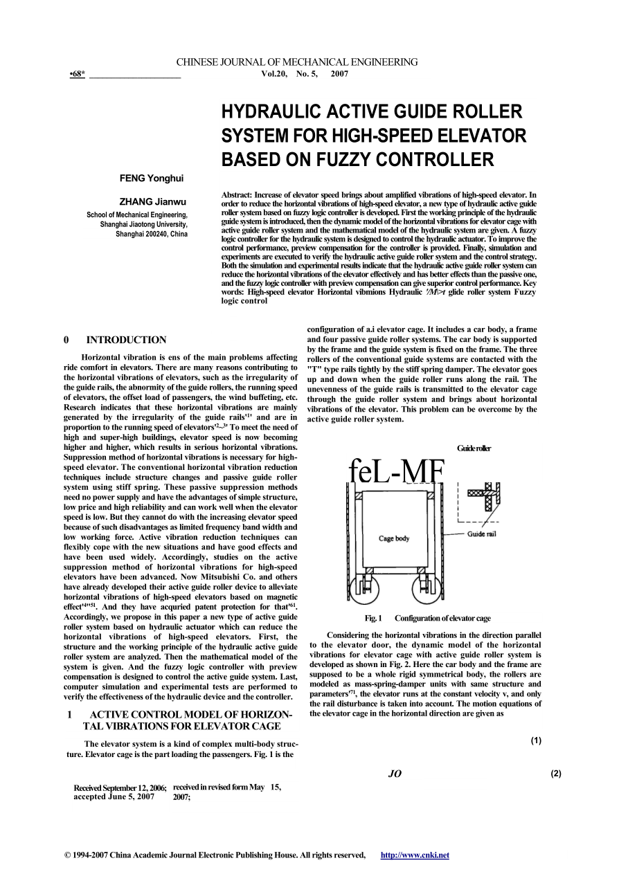
14、e passengers. Fig. 1 is theconfiguration of a.i elevator cage. It includes a car body, a frame and four passive guide roller systems. The car body is supported by the frame and the guide system is fixed on the frame. The three rollers of the conventional guide systems are contacted with the T type r
15、ails tightly by the stiff spring damper. The elevator goes up and down when the guide roller runs along the rail. The unevenness of the guide rails is transmitted to the elevator cage through the guide roller system and brings about horizontal vibrations of the elevator. This problem can be overcome
16、 by the active guide roller system.Guide rollerfeL-MFFig. 1 Configuration of elevator cage(1)Considering the horizontal vibrations in the direction parallel to the elevator door, the dynamic model of the horizontal vibrations for elevator cage with active guide roller system is developed as shown in
17、 Fig. 2. Here the car body and the frame are supposed to be a whole rigid symmetrical body, the rollers are modeled as mass-spring-damper units with same structure and parameters71, the elevator runs at the constant velocity v, and only the rail disturbance is taken into account. The motion equation
18、s of the elevator cage in the horizontal direction are given asReceived September 12, 2006; accepted June 5, 2007received in revised form May 15, 2007;JO(2) 1994-2007 China Academic Journal Electronic Publishing House. All rights reserved, CHINESE JOURNAL OF MECHANICAL ENGINEERING69*CylinderCylinder
19、 bracket. Roller level -OHSV. Accumulator -Oil boxPressure sensor ControllerFig. 3 Configuration of the hydraulic active guide roller2.2 Mathematical modelsThe equations of pressure and fluid flow of the hydraulic cylinder are shown as(4) (5)AL0+xc-x,)p+ A(x, - ir) = A?KPiston rod surface area-Initi
20、al displacement of the piston -Displacement of the roller brackets*rP K-Aq-9i-Qo-1*-Displacement of the guide roller -Hydraulic pressure in the cylinder -Oil bulk modulus -Fluid flow of the cylinder -Fluid flow of IHSV -Fluid flow of OHSV-Compressible fluid flow between the accumulator and the cylin
21、der So the active control force produced by the hydraulic actuator can be expressed as followsF,=pA(6)where the sign in Eq. (6) is positive when i is equal to 1 or 3, and is negative wheni is equal to 2 or 4.The fluid flow equations of the high-speed ON/OFF valves are shown asP)2(P,(7)9i = cddri2(PP
22、2) P(8) )p(10)where me-J-x-0 -Mass of the elevator cage-Moment of inertia of the elevator cage-Displacement of the elevator cage-Rotation angle of the elevator cage-Vertical distance between the guide roller and theFrcenter of the elevator cage -Active control force, produced by the actuator(ACT),=1
23、,-, 4,4,*rltc,|act( m,mV.A0%|Ewhere (3)f$HXW3JCr3XXr4*w4Fig. 2 Dynamic model of horizontal vibrations for sleviiior The motion equations of the guids rollers art given as xrl = -*r( - xt) + cr(xrt - -xw/) - F-,where m,Mass of the guide rollerk,Spring constant of the rollerc,Damper constant of the ro
24、llerxTlDisplacement of the rollerxWJ-Rail disturbance*wl(0=*w3(+o) *w2(0=*w4(+o)t-2lUf+U 0uf+u 1(11)uf + up 0 u,+u9-(12)ut+up -luf+up0Controllerwhere f is the output of FLC and up is the output of PCFeedforward control-1.0 -0.8 -0.6 -0.4 -0.2 0 0.2 0.4 0.6 0.8 1.0Derivative of p pNB NM NS PSZE PM PB
25、1-1.0 -0.8 -0.6 -0.4 -0.2 0 0.2 0.4 0.6 0.8 1.0 Output of FLC f Fig. 5 Membership functions of fuzzy variablesTvhle 1 Fizz) control rulesDfrivativvof /Oi! p.cssure of actuator pPNBNMNSZEPSPMPBNBPBPBPMPSZENSNSNMPBPBPMPSZENSNMNSPBPMPSZENSNMNMZEPBPMPSZENSNMNBPSPMPMPSZENSNMNBPMPMPSZENSNMNBNBPBPSPSZENSNM
26、NBNBPreview controllerFeedback controliConvenor3.2 Preview controllerThe preview controller is a feedforward loop. It is just a compensation for the FLC. As the rail disturbance varies at all time, the preview control Up is assumed to beFuzzy controllernp(0 = a*(r)xw(/ + r)dr(13)HSV_ Hydraulic cylin
27、derRollerFig. 4 Block diagram of controller3.1 Fuzzy logic controllerThe fuzzy logic controller is a feedback loop. It is composed of a fuzzification interface, fuzzy rule base, decision making logic and defuzzification interface. Fuzzification is the process which transforms input signal into fuzzy
28、 sets. The input signal of the FLC is the oil pressure of actuator p and its derivative p . The output signal Uf means the duty ratio of PWM signal for HSV. When f is positive, IHSV will be on and the OHSV will be off. When wf is negative, the IHSV will be off and the OHSV will be on. When u( is zer
29、o, both valves will be off. The input signal p, p and the output signal Uf vary in the interval 0, pm, -&pm, ApJ and -1, 1, respectively. Their universe of discourse are defined as 0, 1, -1, 1 and -1, 1. The linguistic variables of the input and output signals are defined as PB, PM, PS, ZE, NS, NM a
30、nd NB. Triangular and trapezoid membership functions are used for the fuzzy variables, which are shown in Fig. 5. The objective of control is contained in the fuzzy rule base in the form of the linguistic variables using the fuzzy conditional statement. It is summarized in Table 1. The construction
31、rule is as follows: When the error between p and po is big, the error should be minimized as quickly as possible; When the error between p and po is small, the overshoot should be avoided to keep the system stable. The most widely used center of gravity method is applied here to defuzzify the output
32、.where a is a negative constant, T is the width of the preview time window which depends on the delay time of the hydraulic system, k is the weight of the disturbance displacement xw it increases when the distance between the sampling place and the roller location decreases and should satisfy the fo
33、llowing equation(14)= 1f*(OdiAs computer-aided control in reality is digital control, rewrite Eq. (13) and Eq. (14) in discrete form81(15) (16)pO)=a*p(XO+oA/ZM0=iwhere m is the number of preview steps, j represents the current sampling time and A/ is the sampling cycle. Suppose*(/) = exp(-p-;)(17)wh
34、ere P is a positive constant. Eq. (17) can be normalized as*(/)(18)U0 =I*(04 SIMULATION STUDYBased on the mathematical model in this paper, simulation study is carried out using MATLAB. Table 2 shows part model94- China ca emic JnaEetoicsius At eh/enCHINESE JOURNAL OF MECHANICAL ENGINEERING71 30para
35、meters. Set the objective pressure value as 2.5 MPa. Permitted error range of 0.1 MPa is allowed. Take the measured rail disturbance as the input signal. Fig. 6 shows the curve of the guide rail unevenness. Fig. 7 shows the simulation results. Fig. 7a is the acceleration response with passive guide
36、roller. From the simulation results we can see that the maximal value is 0.278 7 m s2, the root mean square value is 0.090 1 m s2. The maximal value is head and shoulders above the boundary 0.15 m s2 specified by China Elevator Standards GB/T 10058-1997 and the ride comfort can be affected seriously
37、. Fig. 7b and Fig. 7e are the acceleration curve and the pressure curve with the hydraulic active guide roller system based on the fuzzy logic controller, respectively. The acceleration response is reduced effectively with amplitude of 0.141 9m* s2and the root mean square value is 0.045 6 m s2, whil
38、e the pressure value of the hydraulic actuator exceeds permitted error range. Fig. 7c and Fig. 7f are the acceleration curve and the pressure curve with the hydraulic active guide roller system based on the fuzzy logic controller with preview compensation. A fuzzy logic controller with preview compe
39、nsation brings about ideal results. The maximal value of the acceleration response is 0.129 3 m s2 and the root mean square value is 0.032 4 m s2, and the hydraulic pressure are constrained between 2.4 MPa and 2.6 MPa. The preview compensation utilizes the future information in advance and can count
40、eract the time delay of the hydraulic system in some degree. Fig. 7d shows :ie power spectry.l unsity(PSD) curves of the horizontal vibrations acceleration. The curve of the passive guide roller is displayed in the solid lines. The curve of the hydraulic active guide roller system based on the fuzzy
41、 logic controller is displayed in the dashed lines. The curve of the hydraulic active guide roller system based on the fuzzy logic controller with preview compensation is displayed in the dot-dashed lines. From Fig. 7d we can conclude that the active guide roller system attenuates the vibrations in
42、the low frequency area effectively, especially the vibrations of the main resonant frequencies. The fuzzy logic controller with preview compensation exhibits better control effects.Table 2 Simulation parametersValueParameterMass of the guide roller m,/kg0Mass of the elevator m/kg2.5X103Spring consta
43、nt of the guide roller V(N m1)134Damper constant of the guide roller c,/(kN s m1)671Piston rod surface area A/m13.14X10Oil bulk modulus AVGPa2.55Fluid flow discharge coefficient Q0.72Pressure of supply oil pi/MPa3Pressure of the oil box /VMPa0.101Oil density p/(kg m5)8605rS -5|l owVvAyvAA_!IIIIl_601
44、020304050Rail place z/m(a) Left guide rail70510152025Running time f/s(a) Acceleration response with passive guide roller101520Runr.js i.iie i/s(b) Accelera-oi response: with active guide roller by fuzy ccnryjlei2505101520Running time f/s(c) Acceleration response with active guide roller by fuzzy con
45、troller with preview compensation0.012 0.010 0.008 0.006 0.004 0.002I3 4 5 6 7 1 Frequency /Hz(d) Power spectral density of the acceleration2.70510152025Running time f/s(e) Pressure response with active guide roller by fuzzy controller3030302.6jiiiii_201060304050Rail place z/m (b) Right guide rail F
46、ig. 6 Curve of the guide rail unevenness70101520Running time f/s(f) Pressure response with active guide roller by fuzzycontroller with preview compensationFig. 7 Comparison of the simulation results 1994-2007 China Academic Journal Electronic Publishing House. All rights reserved, 72-FENG Yonghui, e
47、t al: Hydraulic active guide roller system for high-speed elevator based on fuzzy controllerFrom the simulation results we can get the following conclusions: So long as the oil pressure be kept the objective value with permitted error range, the horizontal vibrations of the elevator would be suppres
48、sed effectively by using the hydraulic active guide roller system. Besides, a fuzzy logic controller with preview compensation can improve the system performance.5 EXPERIMENT VERIFICATION5.1 Rig testTo examine the effectiveness of the hydraulic unit and the control system, rig tests are carried out
49、in the lab. Fig. 8 shows the configuration of the test rig and the testing method. The guide rail simulator is taken on by an eccentric wheel. It is driven by a motor and produces sinusoidal wave displacement signal to imitate the uneveness of the guide rail. The hardware of controller is a Single-c
50、hip-microcomputer based system. The 16-bit single-chip micro-controller SAK-C167CR-LM of infineon family is chosen as the MCU chip. Experimental results are sent to PC by CAN communication. The photo of the test rig is presented in Fig. 9. Set the objective pressure value as 2.5 MPa with permitted e
51、rror range of 0.1 MPa, and the sinusoidal wave signal frequency is l.S Hz. Experimental results are shown in Fig. 10.preview compensation. We can see that the curve has only lighter undulations confined in the permitted range. The hydraulic unit and the control system can work properly.5.2 Real elevator testReal elevator tests are executed in an elevator experimental tower. As the low
- 温馨提示:
1: 本站所有资源如无特殊说明,都需要本地电脑安装OFFICE2007和PDF阅读器。图纸软件为CAD,CAXA,PROE,UG,SolidWorks等.压缩文件请下载最新的WinRAR软件解压。
2: 本站的文档不包含任何第三方提供的附件图纸等,如果需要附件,请联系上传者。文件的所有权益归上传用户所有。
3.本站RAR压缩包中若带图纸,网页内容里面会有图纸预览,若没有图纸预览就没有图纸。
4. 未经权益所有人同意不得将文件中的内容挪作商业或盈利用途。
5. 装配图网仅提供信息存储空间,仅对用户上传内容的表现方式做保护处理,对用户上传分享的文档内容本身不做任何修改或编辑,并不能对任何下载内容负责。
6. 下载文件中如有侵权或不适当内容,请与我们联系,我们立即纠正。
7. 本站不保证下载资源的准确性、安全性和完整性, 同时也不承担用户因使用这些下载资源对自己和他人造成任何形式的伤害或损失。
