 外文文献及翻译

《外文文献及翻译》由会员分享,可在线阅读,更多相关《外文文献及翻译(18页珍藏版)》请在装配图网上搜索。
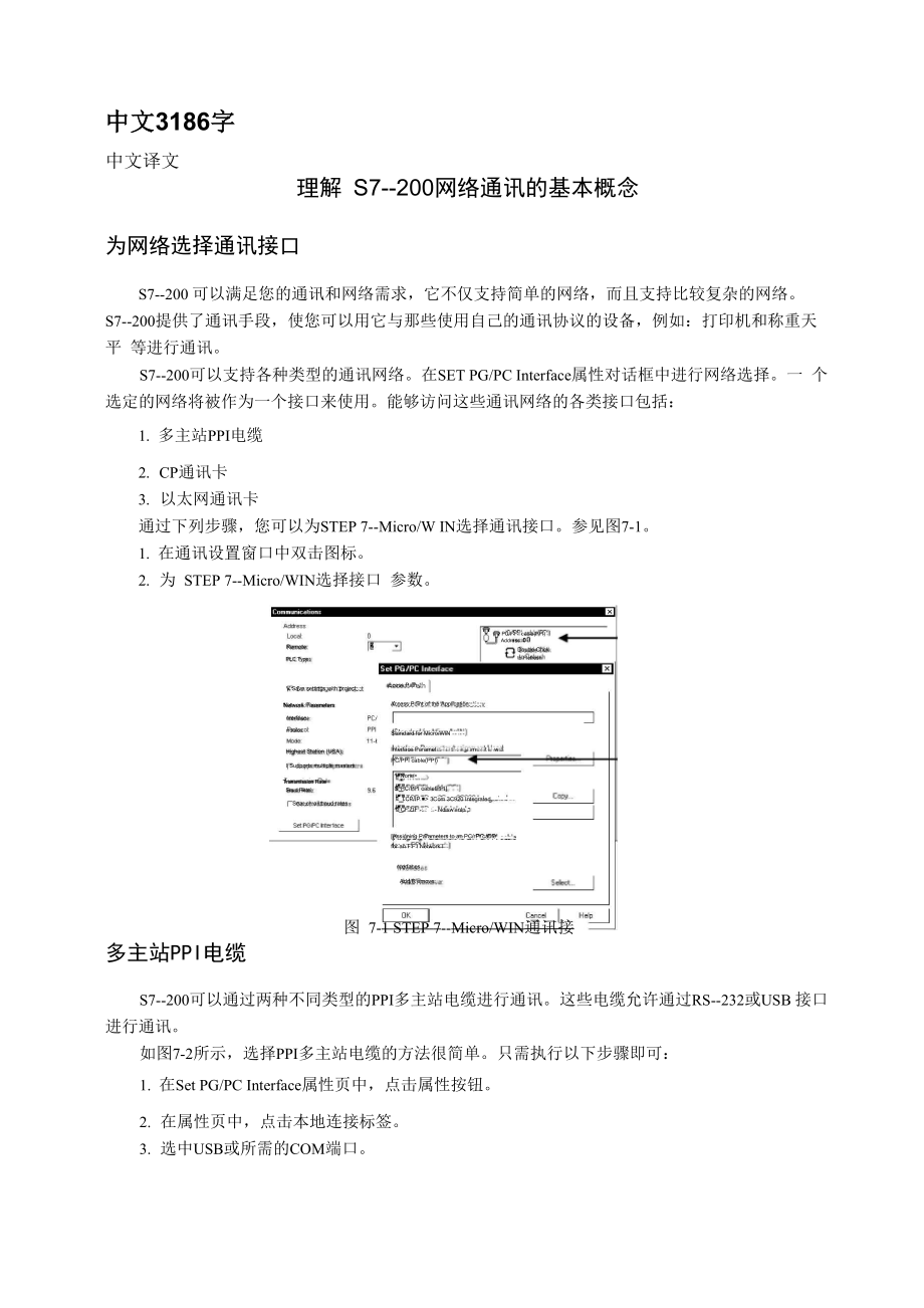
1、中文3186字中文译文理解 S7-200网络通讯的基本概念为网络选择通讯接口S7-200 可以满足您的通讯和网络需求,它不仅支持简单的网络,而且支持比较复杂的网络。S7-200提供了通讯手段,使您可以用它与那些使用自己的通讯协议的设备,例如:打印机和称重天平 等进行通讯。S7-200可以支持各种类型的通讯网络。在SET PG/PC Interface属性对话框中进行网络选择。一 个选定的网络将被作为一个接口来使用。能够访问这些通讯网络的各类接口包括:1. 多主站PPI电缆2. CP通讯卡3. 以太网通讯卡通过下列步骤,您可以为STEP 7-Micro/W IN选择通讯接口。参见图7-1。1.
2、在通讯设置窗口中双击图标。2. 为 STEP 7-Micro/WIN选择接口 参数。Remote:PLC Type:access PathV Save settings with projectAccess Point of the Application:Network Parametersnterface:rrotaco:Standard for Micro/WlNHighest Station (USA):I Supports multiple mastersTransmission RateSaud RateSear ch all baud ratesnterfacesAdd/R em
3、ove:图 7-1 STEP 7-Micro/WIN通讯接口Assigning Parameters to an PC/rPI cablefor an FFI Network ISPC/PPI cablefPPITCP/IP 3Com 3C920 Integrated .TCFZIF1-::- NdiswanlpPU/FFI cable(PPI)Address: 0Doube-Chckto FlefreshInterface Paramet已口型:i口门m亡门t lw已匚I:PC/PPI cable(PPI)多主站PPI电缆S7-200可以通过两种不同类型的PPI多主站电缆进行通讯。这些电缆允
4、许通过RS-232或USB 接口进行通讯。如图7-2所示,选择PPI多主站电缆的方法很简单。只需执行以下步骤即可:1. 在Set PG/PC Interface属性页中,点击属性按钮。2. 在属性页中,点击本地连接标签。3. 选中USB或所需的COM端口。提示请注意,一次只能使用一个USB接口。提示本手册的实例使用的是RS-232/PPI多主站电缆。原先的PC/PPI电缆已RS-232/PPI多主站电缆 替代。另外,USB/PPI电缆也适用于这些实例。关于这些电缆的订货号,可参见附录。在 PROFIBUS 网络上使用主站和从站器件。S7-200支持主从网络,并能在PROFIBUS网络中充当主站
5、或从站,而STEP 7-Micro/WIN只能 作为主站。主站网络上的主站器件可以向网络上的其它器件发出要求。主站也可以对网络上其它主站的要求作出 响应。典型的主站器件包括:STEP 7-Micro/WIN TD200等HMI产品和S7-300或S7-400 PLG 在 向其它S7-200发出请求以获取信息(点对点通讯)时,S7-200是作为主站的。提示如果网络上有其它主站,TP070将无法工作。从站配置为从站的器件只能对其它主站的要求作出响应,自己不能发出要求。对于多数情况7-200 被配置为从站。作为从站,S7-200响应主站的要求。作为从站时,S7-200将负责响应来自某网络主 站器件(
6、如操作员面板或STEP 7-Micro/WlN)的请求。设置波特率和站地址数据通过网络传输的速度是波特率。其单位通常为Kbaud或者Mbaud。波特率用于量度在给定时 间内传输数据的多少。比如,19.2k的波特率即表示传输速率为每秒19200比特。在同一个网络中通讯 的器件必须被配置成相同的波特率。因此,网络的最高波特率取决于连接在该网络上的波特率最低的 设备。表7-1中列出了 S7-200支持的波特率。表 7-1 S7-200支持的波特率网络波特率标准网络9.6K 到 187.5K使用EM2779.6K 到 12M自由口模式1200 到 115.2K在网络中要为每个设备指定唯一的站地址。唯一
7、的站地址可以确保数据发送到正确的设备或者来 自正确的设备o S7-200支持的网络地址为从0到126。如果某S7-200带有两个端口,那么每个端口 都会有一个网络地址。表7-2列出了 S7-200设备的缺省(工厂)设置。表 7-2 S7-200设备的缺省站地址S7-200 设备缺省地址STEP 7-Micro/WIN0HMI (TD200、TP 或 OP)1S7-200 CPU2为 STEP 7-Micro/WIN 设置波特率和站地址您必须为STEP 7-Micro/W IN配置波特率和站地址。其波特率必须与网络上其它设备的波特率一 致,而且站地址必须唯一。通常,您不需要改变STEP 7-Mi
8、cro/WIN的缺省站地址0。如果网络上还含有其它编程工具包, 那么您可能需要改动STEP 7-Micro/W IN的站地址。如图7-3所示,为STEP 7-Micro/WIN配置波特率和站地址非常简单。在操作栏中点击通讯图标,图 7-3 配置 STEP 7-Micro/WIN然后执行以下步骤:.Access: Hoi nt ot the .application:臣 Save settin;Standard for Micro/WINInterface Parameter Assiqrment Used:|PC.-PPI cat.lefPPIMitrcAVIN -: F匚乍曰 G-ableP
9、FINetwork ParameInterface:Protocol:1. 在通讯设置窗口中双击图标。2. 在Set PG/PC Interface对话框中点击属性按钮。3. 为 STEP 7-Micro/WIN选择站地址。4. 为 STEP 7-Micro/WIN选择波特率。为 S7-200 设置波特率和站地址您也必须为 S7-200 配置波特率和站地址。 S7-200 的波特率和站地址存储在系统块中。在为 S7-200设置了参数之后,您必须将系统块下载至S7-200中。每一个S7-200通讯口的波特率缺省设 置为9.6k,站地址的缺省设置为2。如图7-4所示,使用STEP 7-Micro/
10、WIN为S7-200设置波特率和站地址。您可以在操作栏中点击 系统块图标或者在命令菜单中选择View Component System Block然后执行以下步骤:1. 为 S7-200选择站地址。2. 为 S7-200选择波特率。3. 下载系统块到S7-200。提示可以选择各种波特率。在下载系统块期间,STEP 7-Micro/WIN将会验证所选的波特率。如果选 定的波特率可能会妨碍STEP 7-Micro/W IN与其它S7-200进行通讯,那么它将不被下载。设置远端地址在将新设置下载到S 7 - 2 0 0之前,您必须为STEP 7-Micro/WIN (本地)的通讯(COM)口 和S7
11、- 200 (远端)的地址作配置,使它与远端的S7-200的当前设置相匹配。如图7-5所示。在下载了新设置后,您可能需要重新配置PG/PC接口波特率设置(如果新设置与远端S7-200的 设置不同)。关于波特率的配置,可参考图7-3。CommunicationsAddressLocal:Remote:PC/PPI cablePPIAddress: 0PLC Type:G Double-Click to Refresh7 Save settings with projectNetwork ParametersInterface:PC/PPI cableC0M 1Protocol:PPIMode:1
12、1-bitHighest Station (HSA):I- Supports multiple mastersTransmission RateBaud Rate:9.6 kbps厂 Search all baud ratesSet PG/PC InterfaceCancel图 7-5 配置 STEP 7-Micro/WIN在网络上寻找S7200 CPU您可以寻找并且识别连接在网络上的S7-200。在搜索S7-200时,您也可以寻找特定波特率上的 网络或所有波特率上的网络。只有在使用PPI多主站电缆时,才能实现全波特率搜索。若在使直P卡进行通讯的情况下,该 功能将无法实现。搜寻从当前选择的波特
13、率开始。1. 打开通讯对话框并双击刷新图标开始搜寻。2. 要使用所有波特率搜寻,选中在所有波特率下搜寻复选框。为网络选择通讯协议下面是S7-200 CPU所支持的协议的总览。1点对点接口(PPI)2. 多点接口(MPI)3. PROFIBUSCommunicationsAddressLocal:Remote:PLC Type:PC/PPI cable(PPI)Address: 0GDoub le-Click to Refresh磺 Save settings with projectNetwork ParametersInterface:PC/PPIcablefCOM1)Protocol:PP
14、IMode:11-bitHighest Station (HSA):I- Supports multiple mastersTransmission RateBaud Rate:9.6 kbpsI- Sear ch all baud ratesSet PGJPC InterlaceOKCancel图7-6搜索网络上的CPU在开放系统互联(OSI)七层模式通讯结构的基础上,这些通讯协议在一个令牌环网络上实现。 令牌环网络符合欧洲标Ben 50170中定义的PROFIBUS标准。这些协议是非同步的字符协议,有 位起始位、8位数据位、偶校验位和1位停止位。通讯结构依赖于特定的起始字符和停止字符、源和
15、目的站地址,报文长度和数据校验和。在波特率一致的情况下,这些协议可以同时在一个网络上运行,并且互不干扰。如果带有扩展模块CP243-1和CP243-1 IT,那么S7-200也能运行在以太网上。PPI 协议PPI是一种主-从协议:主站器件发送要求到从站器件,从站器件响应,参见图7-7。从站器件不 发信息,只是等待主站的要求并对要求作出响应。主站靠一个PPI协议管理的共享连接来与从站通讯PPI并不限制与任意一个从站通讯的主站数量, 但是在一个网络中,主站的个数不能超过32。图7-7 PPI网络如果在用户程序中使能PPI主站模式,S7-200 CPU在运行模式下可以作主站。(参见附录B中 SMB3
16、0的描述)在使能3PI主站模式之后,可以使用网络读写指令来读写另外一个7-200。当S7-200 作PPI主站时,它仍然可以作为从站响应其它主站的请求。PPI高级允许网络设备建立一个设备与设备之间的逻辑连接。对于PI高级,每个设备的连接个数 是有限制的。S7-200支持的连接个数如表7-3所示。所有的S7-200CPU都支持PPI和PPI高级协议,而 EM277模块仅仅支持PPI高级协议。表7-3 S7-200 CPU和EM277模块的连接个数模块波特率连接数表7-3 S7-200 CPU和EM277模块的连接个数模块波特率波特率连接数S7-200CPU 通讯口0通讯口 19.6k、19.2k
17、或187.5k49.6k、19.2k或187.5k4EM2779.6k到12M6 (每个模块)MPI 协议MPI允许主主通讯和主从通讯,参见图7-8。与一个S7-200 CPU通讯,STEP 7-Micro/WIN建立 主-从连接。MPI协议不能与作为主站的S7-200 CPU通讯。网络设备通过任意两个设备之间的连接通讯(由MPI协议管理)。设备之间通讯连接的个数受 S7-200CPU或者EM277模块所支持的连接个数的限制S7-200支持的连接个数如莉-3所示。对于MPI协议,S7-300和S7-400 PLC可以用XGET和XPUT指令来读写S7-200的数据。要得到更多关于这些指令的信息
18、,参见7-300或者S7-400的编程手册。STEP7-Micro/WINMasterS7-200: Slave,uS7-300: Master|133图7-8 MPI网络PROFIBUS 协议PROFIBUS协议通常用于实现与分布式/O(远程I/O)的高速通讯。可以使用不同厂家的PROFIBUS 设备。这些设备包括简单的输入或输出模块、电机控制器和LC。PROFIBUS网络通常有一个主站和若干个/O从站,参见图7-9。主站器件通过配置可以知道/O从站的类型和站号。主站初始化网络使网络上的从站器件与配置相匹配。主站不断地读写从站的数据。图 7-9 PROFIBUS网 络。图 7-9 PROFI
19、BUS网 络当一个DP主站成功配置了一个DP从站之后,它就拥有了这个从站器件。如果在网上有第二个主 站器件,那么它对第一个主站的从站的访问将会受到限制。TCP/IP协议通过以太网扩展模块CP243-1)或互联网扩展模块CP243-1 IT),S7-200将能支持TCP/IP以 太网通讯。表7-4列出了这些模块所支持的波特率和连接数。表7-4以太网模块(CP243-1)和互联网模块(CP243-1 IT)的连接数。表7-4以太网模块(CP243-1)和互联网模块(CP243-1 IT)的连接数模块波特率连接数以太网(CP243-1)模块10到100兆8个普通连接互联网(CP243-1 IT)模块
20、1 个 STEP 7-Micro/WIr连接若需更多 信息,可参考SIMATIC NET CP243-1工业以太 网通讯处理 器手册或SIMATICNETCP243-1 IT工业以太网及信息技术通讯处理器手册。英文资料原文Understanding the Basics of S7-200 Network CommunicationsSelecting the Communication Interface for Your Networkby Moniruzzaman, Mohammad.; M.A.Sc.; Concordia University (Canada).; 2006;The
21、S7-200 is designed to solve your communications and networking needs by supporting not only the simplest of networks but also supporting more complex networks. The S7-200 also provides tools that allow you to communicate with other devices, such as printers and weigh scales which use their own commu
22、nications protocols.The S7-200 supports many different types of communication networks. The selection of a network is performed within the Set PG/PC Interface property dialog. A selected network is referred to as an Interface. The different types of interfaces available to access these communication
23、 networks are:1. PPI Multi-Master cables2. CP communication cards3. Ethernet communication cardsTo select the communication interface for STEP 7-Micro/WIN, you perform the following steps. SeeFigure 7-1.1. Double-click the icon in the Communications Setup window.2. Select the interface parameter for
24、AddressRemote:PLC TVPB:Access PathV Save settings with projectAccess Point ot the .application:Network Parametersnterface:Prohjcu Standard for Micrm.-WlN IHighest Station (HSA:I Supports multiple mastersSear ch all baud ratesSet PGjPC nterfacenterfacesAdd/H emove:Figure 7-1PMicro/WIN Comm山nications
25、InterfaceAssigning Parameters to an rC/rrl cablefor an FFI Network ITransmission RateSaud Rate尊 MPC/PPI cable(PPI)冏 TCF7IF1 - 3Com 3C920 Integrated .TL:F7IF- NdiswanlpPU/PFI cable(PPIAddress: 0Dciube-Chckto RefreshInterface Parameter Assignment Used:FC/FFI cable(PPI)PPI Multi-Master CablesThe S7-200
26、 supports communication through two different types of PPI Multi-Mastercables. These cable types permit communication through either an RS-232 or a USB interface.As shown in Figure 7-2, selecting the PPI Multi-Master cable type is simple.oYu perform the followingsteps:1. Click the Properties button
27、on the Set PG/PC Interface property page.2. Click the Local Connection tab on the Properties page.3. Select the USB or the desired COM port.Set PG/PC InterfaceAccess Path .Access Point of the .Application:IStandard for KlicroA-VINInterface Parameter Assignment Used:IFC/FFI cabletFFl)FMp飢应:| *HFC/FFI
28、 cabletFFl)零 TCP/IP - 3Com 3C920 Integrated .口叭STCP/IP-NdisWanlp.Assigning for an PPIEl - PC/FPIInterfaceAdd/FlfConr.E-.Dr. h:.IWX:rjCfiOK|CGMI.Figure ,7 2 PPI 4u1ti 4astor CHble Selection 逾 | ttf-jJ | C*rtl | MetTipPlease note that only one USB cable can be used at a time.TipExamples in this manual
29、 use the RS-232/PPI Multi-Master cable. The RS-232/PPI Multi-Master cable replaces the previous PC/PPI cable. A USB/PPI Multi-Master cable is also available. Refer to Appendix E for order numbers.Using Master and Slave Devices on a PROFIBUS NetworkThe S7-200 supports a master-slave network and can f
30、unction as either a master or a slave in a PROFIBUS network, while STEP 7-Micro/WIN is always a master.MastersA device that is a master on a network can initiate a request to another device on the network. A master can also respond to requests from other masters on the network. Typical master device
31、s include STEP 7-Micro/WIN, human-machine interface devices such as a TD 200, and S7-300 or S7-400 PLCs. The S7-200 functions as a master when it is requesting information from another S7-200 (peer-to-peer communications).TipA TP070 will not work on a network with another master device.SlavesA devic
32、e that is configured as a slave can only respond to requests from a master device; a slave never initiates a request. For most networks, the S7-200 functions as a slave. As a slave device, the S7-200 responds to requests from a network master device, such as an operator panel or STEP 7-Micro/WIN.Set
33、ting the Baud Rate and Network AddressThe speed that data is transmitted across the network is the baud rate, which is typically measured in units of kilo baud (kbaud) or mega baud (Mbaud). The baud rate measures how much data can be transmitted within a given amount of time. For example, a baud rat
34、e of 19.2 kbaud describes a transmission rate of 19,200 bits per second.Every device that communicates over a given network must be configured to transmit data at the same baud rate. Therefore, the fastest baud rate for the network is determined by the slowest device connected to the network. Table
35、7-1 lists the baud rates supported by the S7-200.Table 7-1 Baud Rates Supported by the S7-200NetworkBaud RateStandard Network9.6 kbaud to 187.5 kbaudUsing an EM 2779.6 kbaud to 12 MbaudFreeport Mode1200 baud to 115.2 kbaudThe network address is a unique number that you assign to each device on the n
36、etwork. The unique network address ensures that the data is transferred to or retrieved from the correct device. The S7-200 supports network addresses from 0 to 126. For an S7-200 with two ports, each port has a network address. Table 7-2 lists the default (factory) settings for the S7-200 devices.T
37、able 7-2 Default Addresses for S7-200 DevicesS7-200 DeviceDefault AddressSTEP 7-Micro/WIN0HMI (TD 200, TP or OP)1S7-200 CPU2Setting the Baud Rate and Network Address for STEP 7-Micro/WINYou must configure the baud rate and network address for STEP 7-Micro/WIN. The baud rate must be the same as the o
38、ther devices on the network, and the network address must be unique.Typically, you do not change the network address (0) for STEP 7-Micro/WIN. If your network includes another programming package, you might need to change the network address for STEP 7-Micro/WIN.As shown in Figure 7-3, configuring t
39、he baud rate and network address for STEP 7-Micro/WINis simple. After you click the Communications icon in the Navigation bar, you perform the following steps:1. Double-click the icon in the Communications Setup window.2. Click the Properties button on the Set PG/PC Interface dialog box.3. Select th
40、e network address for STEP 7-Micro/WIN.4. Select the baud rate for STEP 7-Micro/WIN.AddressFl emote:PLC Type:眉 Save settiniNetwork Parame2Laual Lnnne匚-Station ParametersP.dcress3T irneuui::I M ultiple M ast er N etwork4Transmission Hate:Highest Node .address:Figure 7-3 Configuring STE7-Micro/WIN-Nel
41、work Parameters厂 Ad vanced PPIMicro/WlH FLA尸尸I G-ablelFFlI b tandard for M icro/w INI1 nterface:戶匚护戶 1 cat.le|;PPI;|Protocol:遷 Mode:l3 PC.PFI c:at.lefPPnQProperties - PC/PPI tabl皂(PPI)Irit&rrsce Faiameter Assiqnment Used:Setting the Baud Rate and Network Address for the S7-200Youmust also configure
42、the baud rate and network address for the S7-200. The system block of theS7-200 stores the baud rate and network address. After you select the parameters for the S7-200, you must download the system block to the S7-200.The default baud rate for each S7-200 port is 9.6 kbaud, and the default network
43、address is 2.As shown in Figure 7-4, use STEP 7-Micro/WIN to set the baud rate and network address for the S7-200.After you select the System Block icon in the Navigation bar or select the View Component System Block menu command, you perform the following steps:1. Select the network address for the
44、 S7-200.2. Select the baud rate for the S7-200.3. Download the system block to the S7-200.System BlockAnalog Input Filters | Fulse 匚日t匚h Eitw: | Background Tim已 | Eh-1 匚onfigurations: | Fort(s | Retentive Flanges | Password | Output Table | Input Filters |D efaultsPL 匚.AddressHighest .AddressBaud Ra
45、teRetry CountGap Upd-at已F日匚t匚”1耳I3(range 1.126JfSI|J range 1 . 126j19.6 kbps jJ|2Z瓦耳|日(range 0.8而耳|3(range 1.100)TipConfiguration parameters must be downloaded before they take effect. Not all FLC types support everFig ek 7-4. CoFIfjguriinbgg7-200&CPU 一OKCancelSelection of all baud rate options is p
46、ermitted. STEP 7-Micro/WIN Validates this selection during thedownload of the System Block. Baud rate selections that would prevent STEP 7-Micro/WIN from communicating with the S7-200 are prevented from being downloaded.Setting the Remote AddressBefore you can download the updated settings to the S7
47、-200, you must set both the communications (COM) port of STEP 7-Micro/WIN (local) and the address of the S7-200 (remote) to match the current setting of the remote S7-200. See Figure 7-5.After you download the updated settings, you may need to reconfigure the PG/PC Interface baud rate setting (if di
48、fferent from the setting used when downloading to the remote S7-200). Refer to Figure 7-3 to configure the baud rate.CommunicationsPC/PPI cable(PPI)Address: 0Q Double-Click to RefreshCancelAddressLocal:0Remote:|2三|PLC Type:17 Save settings with projectNetwork ParametersInterface:PC/PPIcable(C0M 1)Pr
49、otocol:PPIMode:11-bitHighest Station (HSA):厂 Supports multiple mastersTransmission RateBaud Rate:9.6 kbps厂 Search all baud ratesSet PGJPC InterfaceFigure 7-5 Configuring STEP 7-Micro/WINSearching for the S7-200 CPUs on a NetworkYou can search for and identify the S7-200 CPUs that are attached to you
50、r network.oYu can also search the network at a specific baud rate or at all baud rates when looking for S7-200s.Only PPI Multi-Master cables permit searching of all baud rates. This feature is not available if communicating through a CP card. The search starts at the baud rate that is currently sele
51、cted.1. Open the Communications dialog box and double-click the Refresh icon to start the search.2. To search all baud rates, select the Search All Baud Rates check box. 2.Selecting the Communications Protocol for Your NetworkThe following information is an overview of the protocols supported by the
52、 S7-200 CPUs.1. Point-to-Point Interface (PPI)2. Multi-Point Interface (MPI)3. PROFIBUS匸 ommunicationsPC/PPI cable(PPI)Address: 0G Double-Click to RefreshAddressLocal:Remote:PLC Type:两 Save settings with projectNetwork ParametersInterface:PC/PPIcable(C0M1)Protocol:PPIMode:11-bitHighest Station (HSA:
53、I- Supports muttiple mastersTransmission RateBaud Rate:9.6 kbpsI- Search all baud ratesFigure 7-6 Searching for CPUs on a NetworkBased on the Open System Interconnection(OSI) seven-layer model of communications architecture, these protocols are implemented on a token ring network which conforms to t
54、he PROFIBUS standard as defined in the European Standard EN 50170. These protocols are asynchronous, character-based protocols with one start bit, eight data bits, even parity, and one stop bit. Communications frames depend upon special start and stop characters, source and destination station addre
55、sses, frame length, and a checksum for data integrity. The protocols can run on a network simultaneously without interfering with each other, as long as the baud rate is the same for each protocol.Ethernet is also available for the S7-200 CPU with expansion modules CP243-1 and CP243-1 IT. PPI Protoc
56、olPPI is a master-slave protocol: the master devices send requests to the slave devices, and the slave devices respond. See Figure 7-7. Slave devices do not initiate messages, but wait until a master sends them a request or polls them for a response.Masters communicate to slaves by means of a shared
57、 connection which is managed by the PPI protocol. PPI does not limit the number of masters that can communicate with any one slave; however, you cannot install more than 32 masters on the network.Figure 7-7 PPI NetworkS7-200 CPUs can act as master devices while they are in RUN mode, if you enable PP
58、I master mode in the user program. (See the description of SMB30 in Appendix D.) After enabling PPI master mode, you can use the Network Read or the Network Write instructions to read from or write to other S7-200s.While the S7-200 is acting as a PPI master, it still responds as a slave to requests
59、from other masters.PPI Advanced allows network devices to establish a logical connection between the devices. With PPI Advanced, there are a limited number of connections supplied by each device. See Table 7-3 for the number of connections supported by the S7-200.All S7-200 CPUs support both PPI and
60、 PPI Advanced protocols, while PPI Advanced is the only PPI protocol supported by the EM 277 module.Table 7-3 Number of Connections for the S7-200 CPU and EM 277 ModulesModuleBaud RateConnectionsS7-200 CPU Port 09.6 kbaud, 19.2 kbaud, or 187.54Port 1kbaud9.6 kbaud, 19.2 kbaud, or 187.5kbaudEM 277 Mo
61、dule9.6 kbaud to 12 Mbaud6 per moduleMPI ProtocolMPI allows both master-master and master-slave communications. See Figure 7-8. To communicate with an S7-200 CPU, STEP 7-Micro/WIN establishes a master-slave connection. MPI protocol does not communicate with an S7-200 CPU operating as a master.Network devices communicate by means of separate connections (managed by the MPI protocol) between any two devices. Communication between devices is limited to the number of connections supported by the S7-200 CPU or EM 277 modules. See Table 7-3 f
- 温馨提示:
1: 本站所有资源如无特殊说明,都需要本地电脑安装OFFICE2007和PDF阅读器。图纸软件为CAD,CAXA,PROE,UG,SolidWorks等.压缩文件请下载最新的WinRAR软件解压。
2: 本站的文档不包含任何第三方提供的附件图纸等,如果需要附件,请联系上传者。文件的所有权益归上传用户所有。
3.本站RAR压缩包中若带图纸,网页内容里面会有图纸预览,若没有图纸预览就没有图纸。
4. 未经权益所有人同意不得将文件中的内容挪作商业或盈利用途。
5. 装配图网仅提供信息存储空间,仅对用户上传内容的表现方式做保护处理,对用户上传分享的文档内容本身不做任何修改或编辑,并不能对任何下载内容负责。
6. 下载文件中如有侵权或不适当内容,请与我们联系,我们立即纠正。
7. 本站不保证下载资源的准确性、安全性和完整性, 同时也不承担用户因使用这些下载资源对自己和他人造成任何形式的伤害或损失。
