 ANSYS静力分析实例

《ANSYS静力分析实例》由会员分享,可在线阅读,更多相关《ANSYS静力分析实例(13页珍藏版)》请在装配图网上搜索。
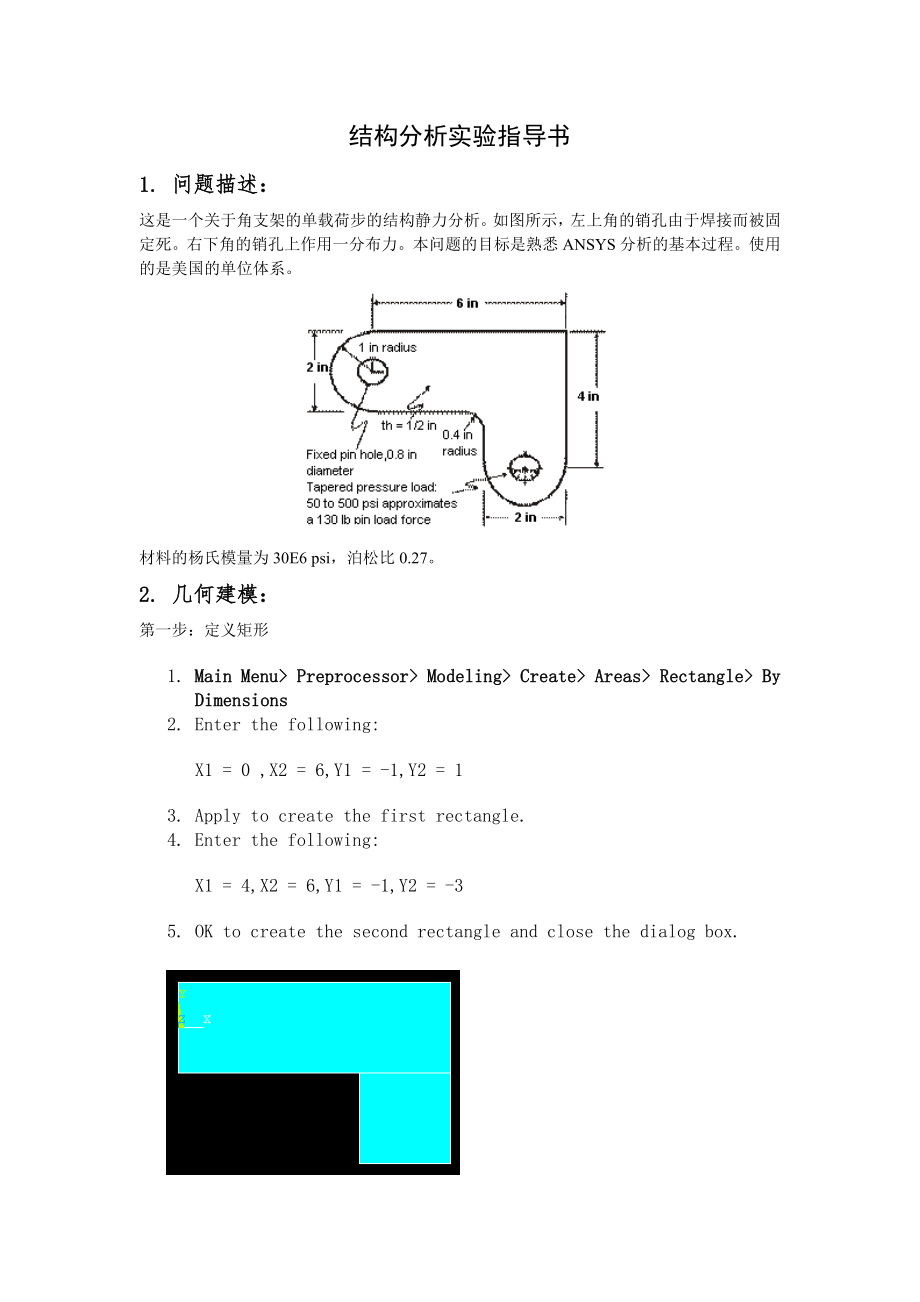
1、结构分析实验指导书 1. 问题描述:这是一个关于角支架的单载荷步的结构静力分析。如图所示,左上角的销孔由于焊接而被固定死。右下角的销孔上作用一分布力。本问题的目标是熟悉ANSYS分析的基本过程。使用的是美国的单位体系。 材料的杨氏模量为30E6 psi,泊松比0.27。 2. 几何建模: 第一步:定义矩形 1. Main Menu Preprocessor Modeling Create Areas Rectangle By Dimensions 2. Enter the following: X1 = 0 ,X2 = 6,Y1 = -1,Y2 = 1 3. Apply to create t
2、he first rectangle. 4. Enter the following: X1 = 4,X2 = 6,Y1 = -1,Y2 = -3 5. OK to create the second rectangle and close the dialog box. 第二步:更改绘图属性和重绘。 1. Utility Menu Plot Ctrls Numbering 2. Turn on area numbers. 3. OK to change controls, close the dialog box, and replot. 4. Toolbar: SAVE_DB. 第三步:更
3、改工作平面为极坐标系并创建第一个圆 1. Utility Menu WorkPlane Display Working Plane (toggle on) 2. Utility Menu WorkPlane WP Settings 3. Click on Polar. 4. Click on Grid and Triad. 5. Enter 0.1 for snap increment. 6. OK to define settings and close the dialog box. 7. Main Menu Preprocessor Modeling Create Areas Circl
4、e Solid Circle 8. Pick center point at:WP X = 0,WP Y = 0 9. Move mouse to radius of 1 and click left button to create circle. 10. OK to close picking menu. 11. Toolbar: SAVE_DB. 第四步:移动工作平面并创建第二个圆 1. Utility Menu WorkPlane Offset WP to Keypoints 2. Pick keypoint at lower left corner of rectangle. 3.
5、Pick keypoint at lower right of rectangle. 4. OK to close picking menu. 5. Main Menu Preprocessor Modeling Create Areas Circle Solid Circle 6. Pick center point at:WP X = 0,WP Y = 0 7. Move mouse to radius of 1 and click left button to create circle. 8. OK to close picking menu. 9. Toolbar: SAVE_DB.
6、 第五步:增加面 1. Main Menu Preprocessor Modeling Operate Booleans Add Areas 2. Pick All for all areas to be added. 3. Toolbar: SAVE_DB. 第六步:创建线倒角 1. Utility Menu PlotCtrls Numbering 2. Turn on line numbering. 3. OK to change controls, close the dialog box, and automatically replot. 4. Utility Menu WorkPl
7、ane Display Working Plane (toggle off) 5. Main Menu Preprocessor Modeling Create Lines Line Fillet 6. Pick lines 17 and 8. 7. OK to finish picking lines (in picking menu). 8. Enter 0.4 as the radius. 9. OK to create line fillet and close the dialog box. 10. Utility Menu Plot Lines 第七步:创建倒角面 1. Utili
8、ty Menu PlotCtrls Pan, Zoom, Rotate 2. Click on Zoom button. 3. Move mouse to fillet region, click left button, move mouse out and click again. 4. Main Menu Preprocessor Modeling Create Areas Arbitrary By Lines 5. Pick lines 4, 5, and 1. 6. OK to create area and close the picking menu. 7. Click on F
9、it button. 8. Close the Pan, Zoom, Rotate dialog box. 9. Utility Menu Plot Areas 10. Toolbar: SAVE_DB. 第八步:将面添加到一起 1. Main Menu Preprocessor Modeling Operate Booleans Add Areas2. Pick All for all areas to be added. 3. Toolbar: SAVE_DB. 第九步:创建第一个销孔 1. Utility Menu WorkPlane Display Working Plane (tog
10、gle on) 2. Main Menu Preprocessor Modeling Create Areas Circle Solid Circle 3. Pick center point at: WP X = 0,WP Y = 0 4. Move mouse to radius of .4 (shown in the picking menu) and click left button to create circle. 5. OK to close picking menu. 第十步:移动工作平面并创建第二个销孔 1. Utility Menu WorkPlane Offset WP
11、 to Global Origin 2. Main Menu Preprocessor Modeling Create Areas Circle Solid Circle 3. Pick center point at: WP X = 0,WP Y = 0 4. Move mouse to radius of .4 (shown in the picking menu) and click left mouse button to create circle. 5. OK to close picking menu. 6. Utility Menu WorkPlane Display Work
12、ing Plane (toggle off)7. Utility Menu Plot Replot 8. Utility Menu Plot Lines 9. Toolbar: SAVE_DB. 第十一步:从支架上减掉销孔 1. Main Menu Preprocessor Modeling Operate Booleans Subtract Areas 2. Pick bracket as base area from which to subtract. 3. Apply (in picking menu). 4. Pick both pin holes as areas to be su
13、btracted. 5. OK to subtract holes and close picking menu. 3. 定义材料:第十二步:设置分析类型 1. Main Menu Preferences 2. Turn on structural filtering. 3. OK to apply filtering and close the dialog box. 第十三步:定义材料属性 1. Main Menu Preprocessor Material Props Material Models 2. Double-click on Structural, Linear, Elast
14、ic, Isotropic. 3. Enter 30e6 for EX. 4. Enter .27 for PRXY. 5. OK to define material property set and close the dialog box. 6. Material Exit 第十四步:定义单元类型和选项1. Main Menu Preprocessor Element Type Add/Edit/Delete 2. Add an element type. 3. Structural solid family of elements. 4. Choose the 8-node quad
15、(PLANE82). 5. OK to apply the element type and close the dialog box. 6. Options for PLANE82 are to be defined. 7. Choose plane stress with thickness option for element behavior. 8. OK to specify options and close the options dialog box. 9. Close the element type dialog box. 第十五步:定义实常数(什么是实常数?)1. Mai
16、n Menu Preprocessor Real Constants Add/Edit/Delete2. Add a real constant set. 3. OK for PLANE82. 4. Enter .5 for THK. 5. OK to define the real constant and close the dialog box. 6. Close the real constant dialog box.4. 划分网格:第十六步:面网格划分1. Main Menu Preprocessor Meshing Mesh Tool2. Set Global Size cont
17、rol. 3. Type in 0.5. 4. OK. 5. Choose Area Meshing. 6. Click on Mesh. 7. Pick All for the area to be meshed (in picking menu). Close any warning messages that appear.8. Close the Mesh Tool. 5. 施加载荷:第十七步:施加位移约束1. Main Menu Solution Define Loads Apply Structural Displacement On Lines2. Pick the four l
18、ines around left-hand hole (Line numbers 10, 9, 11, 12).3. OK (in picking menu).4. Click on All DOF. 5. Enter 0 for zero displacement. 6. OK to apply constraints and close dialog box. 7. Utility Menu Plot Lines 8. Toolbar: SAVE_DB.第十八步:施加分布力1. Main Menu Solution Define Loads Apply Structural Pressur
19、e On Lines2. Pick line defining bottom left part of the circle (line 6). 3. Apply. 4. Enter 50 for VALUE. 5. Enter 500 for optional value. 6. Apply. 7. Pick line defining bottom right part of circle (line 7).8. Apply. 9. Enter 500 for VALUE. 10. Enter 50 for optional value. 11. OK. 12. Toolbar: SAVE
20、_DB. 6. 求解:第十九步:求解1. Main Menu Solution Solve Current LS2. Review the information in the status window, then choose File Close 3. OK to begin the solution. Choose Yes to any Verify messages that appear.4. Close the information window when solution is done. 7. 查看结果:第二十步:读入数据结果1. Main Menu General Pos
21、tproc Read Results First Set第二十一步:绘制变形图1. Main Menu General Postproc Plot Results Deformed Shape2. Choose Def + undeformed. 3. OK. 4. Utility Menu Plot Ctrls Animate Deformed Shape5. Choose Def + undeformed. 6. OK.第二十二步:绘制应力图1. Main Menu General Postproc Plot Results Contour Plot Nodal Solu2. Choose
22、 Stress item to be contoured. 3. Scroll down and choose von Mises (SEQV). 4. OK. 5. Utility Menu Plot Ctrls Animate Deformed Results6. Choose Stress item to be contoured. 7. Scroll down and choose von Mises (SEQV). 8. OK. 9. Make choices in the Animation Controller (not shown), if necessary, then choose Close. 第二十三步:列出约束反力1. Main Menu General Postproc List Results Reaction Solu2. OK to list all items and close the dialog box. 3. Scroll down and find the total vertical force, FY. 4. File Close (Windows). 第二十四步:退出ANSYS软件1. Toolbar: Quit.2. Choose Quit - No Save! 3. OK.
- 温馨提示:
1: 本站所有资源如无特殊说明,都需要本地电脑安装OFFICE2007和PDF阅读器。图纸软件为CAD,CAXA,PROE,UG,SolidWorks等.压缩文件请下载最新的WinRAR软件解压。
2: 本站的文档不包含任何第三方提供的附件图纸等,如果需要附件,请联系上传者。文件的所有权益归上传用户所有。
3.本站RAR压缩包中若带图纸,网页内容里面会有图纸预览,若没有图纸预览就没有图纸。
4. 未经权益所有人同意不得将文件中的内容挪作商业或盈利用途。
5. 装配图网仅提供信息存储空间,仅对用户上传内容的表现方式做保护处理,对用户上传分享的文档内容本身不做任何修改或编辑,并不能对任何下载内容负责。
6. 下载文件中如有侵权或不适当内容,请与我们联系,我们立即纠正。
7. 本站不保证下载资源的准确性、安全性和完整性, 同时也不承担用户因使用这些下载资源对自己和他人造成任何形式的伤害或损失。
