 外文翻译--应用计算机辅助工程设计重型卡车车架

《外文翻译--应用计算机辅助工程设计重型卡车车架》由会员分享,可在线阅读,更多相关《外文翻译--应用计算机辅助工程设计重型卡车车架(11页珍藏版)》请在装配图网上搜索。
1、辅助工程设计重型货车车架Carlos Cosme, Amir Ghasemi and Jimmy Gandevia 摘要:近年来,重型货车市场变得非常的注重重量和降低成本。这对设计工程师是 重大挑战,因为这些车辆被用在各种各样的公路环境,从高速公路到严重的越野 环境。目前的挑战是在不牺牲耐用性和性能降低的前提下满足质量和成本。本文 论述了运用计算机集成、计算机辅助设计和工程软件代码(Pro / Engineer, ADAMS软件和ANSYS)来辅助设计更改车架。特别是,本文集中论述了一个ADAMS多体动力学模型,一个完整的卡车和 拖车来模拟车辆的侧翻稳定性,平顺性,和耐久性载荷。该模型包括一个
2、采用灵 活的框架模型模态综合模式,探讨了有限元分析程序。之间的多体仿真链接与有 限元程序也可以用来传输、加载应力分析有限元模型。所有代码之间紧密连结, 确保新的设计并行计算可快速用于设计和分析。一个说明这是如何 已被使用的技术详细的个案研究也包括在内。简介最近,重卡行业经历了汽车降低成本和重量的大发展。这一直是卡车制造商 的主要挑战,在不牺牲耐用性和性能的前提下,寻找好的方式来优化他们的汽车 设计。由于车架是车辆系统的重要组成部分,它经常被用于完善。本文概述了电脑 辅助工程(CAE)分析更改车架以及这些变化会如何影响车辆性能。重型卡车的 车架是该车辆的骨干,上面集成了主要的卡车组成系统,如车轴
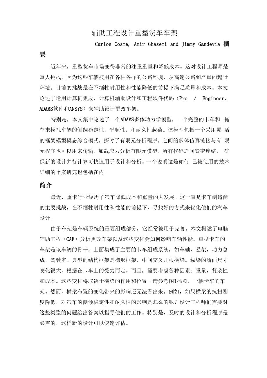
3、,悬架,动力总 成,驾驶室。典型的结构框架是梯形框架,中间交叉几根横梁。纵梁的断面尺寸 变化很大,根据在卡车上的受力而定。而且,需要考虑各种因素:重量,复杂性 和成本。这些变化将取决于横梁的作用和位置。请参考图1插图,一辆卡车的车 架。然而,横梁布置的变化带来的影响还无法看出来。例如,如果横梁的抗扭刚 度降低,对汽车的侧倾稳定性和耐久性的影响是怎么的呢?设计工程师们需要对 这些类型的问题给出答案以指导他们的工作。特别是,及时的设计和分析程序是 必需的,这样新的设计可以快速评估。图1重型载货汽车车架计算机辅助工程在过去的二十年中汽车自动化设计工具CAE得到了巨大的发展。这项技术 的已被很多汽车制
4、造商采用以改善汽车设计来满足快速增长的市场要求。当今的 结构设计通常是使用两个CAE工具:有限元分析(FEA)和多体系统(MSS), 结合CAD提高设计和分析。在过去十五年里,CAD系统已取代绘图板作为首选设计方法。它们使设计 师和工程师能够快速画出卡车零部件,汽车真实模型和设计图纸。先进的CAD 系统功能丰富,如参数化实体建模和大型装配管理。他们已经发展成为主要的数 据库,为工程信息尤其是CAD系统提供下游CAE应用的重要数据。工程师通常使用有限元分析研究结构构件的强度。典型的有限元分析的重点是结 构应力,挠度和自然频率。首先对通常被称为网格的离散结构进行分析。该网格 是由节点和元素组成,而
5、且经常从CAD创建几何系统。这些节点代表位移计算 的结构。他们定义的局部质量,刚度和阻尼性能结构。有关这些数量方程,可以 自动开发节点位移。其他投入,如边界条件,载荷和材料特性,必须是由用户定 义。所有这些效果都需要小心的判断和对有意义的结果进行认真的分析。结果后 处理包括图像变形负载结构,彩色应力轮廓,振型动画。MSS多体系统仿真方法研究了运动部件和组件,并经常用来研究车辆暂停 或车辆的操作和动态响应。一个典型的完整的车型MSS将刚体组成(车轮,车 轴,车架,发动机,驾驶室)模拟成关节连接和理想化力元。MSS代码自动发 展非线性微分方程和代数方程定义模型中的物体运动。该方程在数值上集成刚体
6、位移,速度,加速度和受力。结果以图形和动画显示该系统的运动。至于有限元 分析,CAD数据经常使用MSS的发展模式。CAD几何数据是用于建立MSS的 布局模式,如接头和力量元素的位置。CAD实体模型数据也可以用来估计每个 刚体的位置,质心和惯性特性。作用在刚体上的力可以用作MSS的输入负载, 有限元分析确定该刚体的结构应力。CAE技术在本文所讨论的工具包括基与 CAD的Pro / Engineer,ANSYS进行有限元分析,以及基于ADAMS的MSS。 下面的讨论引用的是某型卡车的车架有限元分析。CAE重型汽车建模如上所述,在目前提供的CAD与CAE工具提供了大量的整合。尽管如此, 这些工具是非
7、常粗略的分析,仍然需要努力分析重型卡车和卡车车架。为了充分 了解车架影响汽车操纵的变化,滚动稳定性,平顺性和持久性,需要一个详细的 MSS模型,可以模拟所有这些影响。使用ADAMS软件代码,建立了 WesterStar 卡车的模型。图二展示了在ADAMS环境下的模型。图2 ADAMS的MSS的模型该模型包括以下几个特点:100刚体180力元45共同元素415度-的自由度1. “Mechanics of Heavy-Duty Trucks and Truck Combinations ,UMTRI Course Notes, July,1995.2. Stasa, Frank L., “Appl
8、ied Finite Element Analysis for Engineers, CBS College Publishing, 1985.3. Ottarsson, Gisli, “Modal Flexibility Method in ADAMS/FLEX, Mechanical Dynamics, Inc., March, 1998.4. “Using ADAMS/FLEX, Mechanical Dynamics, Inc.,1997.5. “ADAMS/Finite Element Analysis Reference Manual, Mechanical Dynamics, I
9、nc., November 15,1994.6. “Pro/MESH and Pro/FEM Post, Users Guide, Parametric Technology Corporation, 1997.7. “ANSYS Structural Analysis Guide, An alysis, Inc.,1994.8. Gillespie, Thomas D., “Fundamentals of Vehicle Dynamics, Society of Automotive Engineers, Inc.,1992.9. Gobessi, Mark and Arnold, Wes,
10、 “The Application of Bonded Aluminum Sandwich Construction Technology to Achieve a Lightweight, Low Cost Automotive Structure, SAE paper 982279.1999-01-3760Application of Computer Aided Engineering in the Design of Heavy-Duty Truck FramesCarlos Cosme, Amir Ghasemi and Jimmy GandeviaWestern Star Truc
11、ks, Inc.Copyright 1999 Society of Automotive Engineers, Inc.ABSTRACTsimulate vehicle handling, roll stability, rideIn recent years the heavy-duty Class 8 truck market has become very focused on weight and cost reduction. This represents a major challenge for design engineers since these vehicles are
12、 used in a wide variety of vocations from highway line haul to logging in severe off-road environments.The challenge is to meet the weight and cost reduction goals without sacrificing durability and performance. This paper discusses the integration of computer aided design and engineering software c
13、odes (Pro/Engineer, ADAMS, and ANSYS) to simulate the effect of design changes to the truck frame .In particular, this paper discuses the development of an ADAMS multi-body dynamics model of a full truck and trailer to performance, and durability loading. The model includes a flexible frame model us
14、ing a component mode synthesisapproach with modes imported from a finite element analysis program. The link between the multi-body simulation and the finite element code is also used to transfer loads back to the finite element model for stress analysis. Tight links between all the codes ensures tha
15、t new design iterations can be quickly evaluated for concurrent design and analysis. A detailed case study showing how this technology has been used is also included.INTRODUCTIONRecently the heavy truck industry has experienced a large push to developvehicles with reduced cost and weight. This has b
16、een a major challenge for truck manufacturersas they look for ways to optimize their vehicle designs without sacrificing durability or performance.Since the truck frame is a major component in the vehicle system, it is often identified for refinement. This paper outlines a computer aided engineering
17、 (CAE) procedure for analyzing changes to the truck frame and how these changes affect vehicle performance .The frame of a heavy truck is the backbone of the vehicle and integrates the main truck component systems such as the axles, suspension, power train, cab, and trailer.The typical frame is a la
18、dder structure consisting of two C channel rails connected by cross-members. The frame rails vary greatly in length and cross-sectional dimensions depending on the truck application. Likewise, the cross-members vary in design, weight, complexity, and cost. These variations will depend upon the cross
19、-member purpose and location. Refer to Figure 1 for an illustrationof a truck frame. However, the effects of changes to the frame and cross-members are not well understood.For example, if the torsional stiffness of a suspension cross-member is lowered, what is the effect on the vehiclesroll stabilit
20、y, handling, ride, and durability? Design engineers require answers to these types of questions to guide them in their work. In particular, a concurrent design and analysis procedure is required so that new designs can be quickly evaluated.Figure 1. Class 8 Heavy-Duty Truck Frame COMPUTER AIDED ENGI
21、NEERINGIn the last twenty years there has been an enormous growth in the development of CAE tools for automotive design. Much of this technology has been adopted by the truck industry as truck manufacturers look to improve their designs in a rapidly growing market. Today structural design is typical
22、ly performed using two CAE tools: finite element analysis (FEA), and multi-body system simulation (MSS). These are combined with computer aided design (CAD) software to improve design and analysis communication.CAD - In the last fifteen years CAD systems have replaced drawing boards as the method of
23、 choice for design. They enable designers and engineers to quickly create realistic models of truck components, vehicle assemblies, and design drawings for manufacturing.Advanced CAD systems are rich in features such as parametric solid model and large assembly management. They have evolved to becom
24、e major databases for engineering information. In particular , CAD systems provide important data for downstream CAE applications.FEA - Finite element analysis is usually used by engineers to study the strength of structural components.Typical FEA activity is focused on analyzing structural stresses
25、, deflections, and natural frequencies. The analysis begins with a discretized representation of a structure known as a mesh. The mesh is composed of nodes and elements and is often created with geometry from a CAD system. The nodes represent points on the structure where displacements are calculate
26、d. The elements are bounded by sets of nodes and enclose areas or volumes. They define the local mass, stiffness, and damping properties of the structure. Equations relating these quantitiesto the nodal displacements are automatically developed by the software codes. Other inputs, such as boundary c
27、onditions, applied loads, and material properties, must be defined by the user. Each of these quantities requires careful judgement for meaningful results to be achieved. Results post-processing includes images of deformed structures under load, coloured stress contours, and mode shape animations.MS
28、S - Multi-body system simulation is used to study the motion of components and assemblies and is often used to study a vehicle suspension or a vehicles handling and ride response. A typical MSS model of a full vehicle will be composed of rigid bodies (wheels, axles, frame , engine, cab, and trailer)
29、 connected by idealized joints and force elements. The MSS code automatically develops the non-linear differential and algebraic equations that define the motion of the bodies in the model. The equations are numerically integrated to produce time histories of rigid body displacements, velocities, ac
30、celerations, and forces. Results are viewed as graphs and animations ofthe system motion. As with FEA, CAD data is often used to develop a MSS model. Geometry data from a CAD assembly is used to establish the layout of the MSS model such as the location of joints and force elements. CAD solid model
31、data is also used to estimate the location of the center-of-mass and the inertial properties of each rigid body. Forces acting on a rigid body from a MSS can be used as input loads to a finite element analysis to determine the structural stresses in that rigid body.The CAE tools discussed in this pa
32、per include Pro/Engineer for CAD, ANSYS for FEA, and ADAMS for MSS. The following discussion references the specific capabilities of these codes in developing a customized environment for the engineering analysis of truck frames.CAE CUSTOMIZATION FOR HEAVY TRUCK MODELLINGAs described above, the curr
33、ent offering of CAD and CAE tools provide a great deal of integration. Nonetheless, these tools are very general in scope and a significant customization effort is required for the analysis of heavy duty trucks and truck frames. To fully understand how changes to the truck frame impact vehicle handl
34、ing, roll stability, ride, and durability requires a detailed MSS model that can simulate all these effects. Using theADAMS software code such a model was developed atWestern Star Trucks. Refer to Figure 2 for a view of the model in the ADAMSenvironment.Figure 2. ADAMS MSS ModelThe model includes th
35、e following characteristics: 100 rigid bodies 180 force elements 45 joint elements 415 degrees-of-freedomThe rigid bodies include the frame, cab, axles, wheels ,engine, hood, radiator, leaf springs, suspension arms, drive shafts, and the trailer. Mass properties for many ofthese bodies were estimate
36、d using simplified solid models in Pro/Engineer. The force elements include linear and non-linear bush ielements that model rubber isolators, such as the cab and engine mounts. Non-linear single component forces are used to model air springs and shock absorbers. Property data for these elements are
37、derived from tests performed by component suppliers. Revolute joints andspherical joints are used to model connection points, such as wheel bearings and torque rod pivots, respectively. Pro/Engineer assemblies are used to determine the geometric location of these elements.Since the heavy truck indus
38、try offers a wide variety of vehicle layouts, the locations of many of the trucks subs ystems were made parametric for easy modification. For example, the front axle subassembly(wheels, axles, leaf springs, and shock absorbers) were linked to a variable defining the longitudinal position of the fron
39、t axle. Usingthis technique, truck models with different front axle positions can be quickly developed by changing the value of this variable. This procedure was duplicated for the following subassemblies: rear suspension, cab ,engine ,hood, and fifth wheel and trailer .Tire to road contact is handl
40、ed with the ADAMS built-in tire routines and includes models for tire handling and durability forces. In ADAMS road profiles are representedas a mesh of triangles similar to a finite element mesh. The geometry and mesh for the road profiles are generated with Pro/Engineer. A custom software program
41、isthen used to translate the mesh into two files for ADAMS :a road file format for the solver to determine the tire/road interaction forces, and a graphics format to view the roadduring post-processing animation. These files are stored in a common directory for easy retrieval. Custom control algorit
42、hms were developed to control vehicle speed, steering, and drive torque. These functionscan be quickly modified to execute different vehicle maneuvers such as roll stability, a high speed lane change, or durability bumps similar to a proving ground.After the simulations are run, the forces and torqu
43、es acting on the frame are written to data files. A custom software program is then used to extract the loads at specifictime steps and write them to an ANSYS load file. The load file is then read into ANSYS and applied to a finite element model of the frame. The frame stresses are then calculated u
44、sing an inertial relief solution.In summary, the model uses custom software routines and the existing links between the CAD and CAE codes to create a custom environment for evaluating the performance and durability of a heavy-duty truck. However, the model assumes that the truck frame is a rigid, un
45、der formable body. In reality, the truck frame contains a great dealof flexibility which can impact vehicle performance and stability. As a result, these effects must be captured in the multi-body system simulation.CAE SOLUTION FOR FRAME FLEXIBILITYPREVIOUS TECHNIQUES - In the past, several techniqu
46、es have been employed to capture frame flexibility in a MSS model. Three popular methods are: bushings,mass beam elements, and FEA super element reduction. In the first method the frame is divided into two or more rigid bodies connected together with force elements having bushing-like properties: st
47、iffness and damping in three translational directions and three rotational directions. The bushing properties are adjusted to give the overall frame bending and torsional stiffness.As can be expected, this method is cumbersome to use, and if properly tuned, it will be capable of capturing only the f
48、undamental bending and torsional modes of the frame. In the second method the frame is divided into a large number of rigid bodies interconnected by massless beam elements. This is similar to the bushing method but many more rigid bodies are usually used, and they are connected with massless beam el
49、ements whose equations (Timoshenko beam theory) are better suited to modellingtruck frame rails and cross-members. Nonetheless, it istime consuming to build a frame with this method and careful tuning of the beam elements is still required to capture the frames flexural response. The third method is
50、 the most accurate of the three methods and is based on a finite element representation of the frame. In this method the finite element model is reduced to a super element representation with the overall stiffness and mass properties condensed to a set of master nodes. The reduced model is checked a
51、gainst the original finite element model to ensure that the important frame dynamics are still captured. It is then imported into the MSS environment where the super elements andmaster nodes are converted to an equivalent representation of rigid bodies and force elements. Although this method is bas
52、ed on a finite element solution, it can still be difficult to achieve accurate results. For example, care must be taken in selecting the master nodes to ensure that the mass and stiffness condensation process is accurate.All the methods described above are difficult to use for creating an accurate f
53、lexible model of a truck frame. In general, they are only capable of capturing the basic frame response: the first few bending and torsionalmodes and the gross frame stiffness. If each method is to work, a significant effort is required to tune its properties to match some reference, such as static
54、deflection testing,modal testing, or finite element simulation results. Consequently, neither method is suitable for use in a concurrent design and analysis environment - it would simply take too long to make changes to the model, and it would not have adequate spatial resolution to capture subtle d
55、esign changes to the frame.COMPONENT MODE SYNTHESIS TECHNIQUE -Recent advances in the integration of FEA and MSS have overcome the difficulties in the methods described above .It is now possible to use a finite element model directly in a multi-body simulation using a modal superposition technique k
56、nown as component mode synthesis (CMS).Using modal superposition, the deformation of a structure can be described by the contribution of each of its modes. Normally, a very large number of modes are required to accurately capture the deformations at points where constraints are applied to the struct
57、ure. CMS was developed to alleviate this problem. It combines normal modes with constraint modes. These constraint modes, or static shapes, capture the deformation of key areas of the structure without having to maintain an excessive number of normal modes. As a result, they are computationally more
58、 efficient. The CMS procedure adopted in the ADAMS code is based on a modified version of the Craig-Bampton approach. In this method the structure is considered to have interface points where constraints and forces are applied, and each interface point can have up to six degrees-of-freedom: three tr
59、anslations and three rotations. The motion of the structure is then described by a combination of two sets of modes: constraint modes for the interface points, and fixed interface normal modes. A constraint mode is calculated for each degree-of-freedomof an interface point, and it describes the stat
60、ic shape of the structure when that degree-of-freedom is given a unit deflection while keeping the degrees-of-freedom of all the other interface points fixed. This procedure is repeated to develop a family of constraint modes for all the interface points. Since the constraint modes are static shapes
61、, their frequency information is unknown. The fixed interface normal modes represent the normal modes of the entire structure when all the degrees-of-freedom of all the interface points are held fixed.In this form, the Craig-Bampton modes are not ideally suited for integration with the multi-body eq
62、uations of motion. For example, the constraint modes add rigid body modes which conflict with the ADAMS non-linear rigid body motions. Also, the constraint modes may contain high frequencies that are difficult to solve. In the ADAMS implementation these problems are handled by orthogonalizing the Cr
63、aig-Bampton modes. This identifies the rigid body modes making them easy to disable. It also adds frequency information to the constraint modes which is valuable for setting integration parameters during the multi-body simulation. After orthogonalization, a modified set of modes exist: normal modes
64、for the unconstrained structure (free-free like modes similar to those calculated in a typical FEA eigenvalue run), and the interface degrees-of-freedom. See Ottarsson 3 for a complete description of this method.All the modal calculations described above take place in the ANSYS environment and are p
65、erformed on a finite element model of the frame. To compute the modes, theuser selects the nodes representing the interface points where forces and constraints enter the frame, and then runs a macro that executes the appropriate ANSYS commands. The number of normal modes to include in the calculations are passed as a parameter to the macro. The final set of modes are written to a modal neutral fileMNF) that can be read by ADAMS.The advantage of this modal superposition method are many and include: The frame is represented
- 温馨提示:
1: 本站所有资源如无特殊说明,都需要本地电脑安装OFFICE2007和PDF阅读器。图纸软件为CAD,CAXA,PROE,UG,SolidWorks等.压缩文件请下载最新的WinRAR软件解压。
2: 本站的文档不包含任何第三方提供的附件图纸等,如果需要附件,请联系上传者。文件的所有权益归上传用户所有。
3.本站RAR压缩包中若带图纸,网页内容里面会有图纸预览,若没有图纸预览就没有图纸。
4. 未经权益所有人同意不得将文件中的内容挪作商业或盈利用途。
5. 装配图网仅提供信息存储空间,仅对用户上传内容的表现方式做保护处理,对用户上传分享的文档内容本身不做任何修改或编辑,并不能对任何下载内容负责。
6. 下载文件中如有侵权或不适当内容,请与我们联系,我们立即纠正。
7. 本站不保证下载资源的准确性、安全性和完整性, 同时也不承担用户因使用这些下载资源对自己和他人造成任何形式的伤害或损失。
