 温度监测中英文翻译

《温度监测中英文翻译》由会员分享,可在线阅读,更多相关《温度监测中英文翻译(12页珍藏版)》请在装配图网上搜索。
1、土壤温度测量的设计1. 简介温度是土壤的一个十分重要的环境因素, 它直接影响微生物的活跃性及有机物的分 解,影响 植物的根吸收水分与矿物质,同时它在植物生长率及根的范围上发挥着重要作 用。据统计,植物的 根一般在地下 50 厘米范围内,因此测量这一范围内不同深度的土 壤温度变得十分有意义。目前,土壤温度测量仪器可分为三类。第一种,是利用热敏电阻与土壤温度之间的 关系测量 实际温度。在使用这类仪器前,系统参数需要校正,同时当解决系统遇到的问 题时,十分不便。第 二种是非接触式的土壤测温仪器,它通过红外线测量温度,这种设 备价格昂贵。第三种,通过数字 温度计测量温度。目前,这类仪器不仅可测量一点的
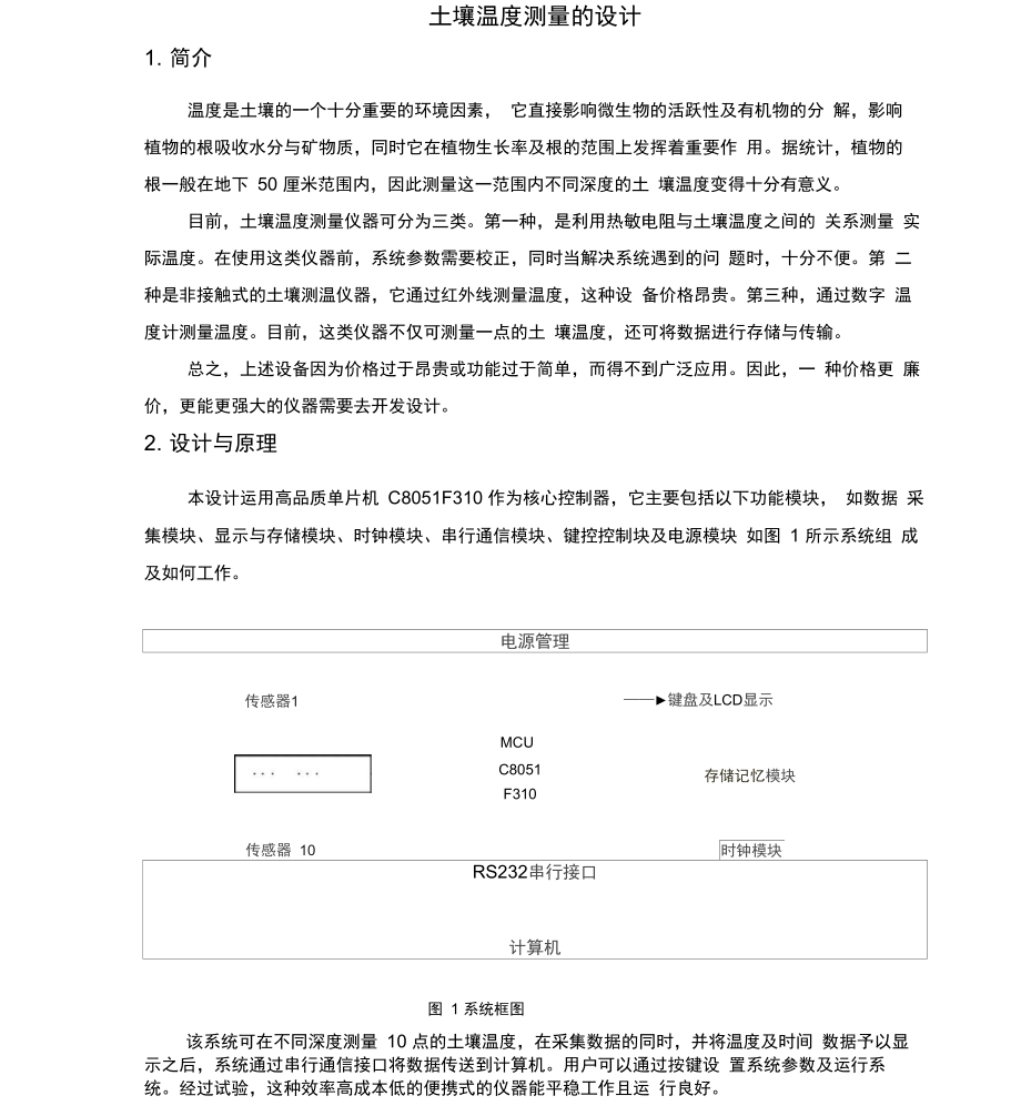
2、土 壤温度,还可将数据进行存储与传输。总之,上述设备因为价格过于昂贵或功能过于简单,而得不到广泛应用。因此,一 种价格更 廉价,更能更强大的仪器需要去开发设计。2. 设计与原理本设计运用高品质单片机 C8051F310 作为核心控制器,它主要包括以下功能模块, 如数据 采集模块、显示与存储模块、时钟模块、串行通信模块、键控控制块及电源模块 如图 1 所示系统组 成及如何工作。电源管理MCU键盘及LCD显示传感器1传感器 10C8051F310存储记忆模块时钟模块RS232串行接口计算机图 1 系统框图该系统可在不同深度测量 10 点的土壤温度,在采集数据的同时,并将温度及时间 数据予以显 示之
3、后,系统通过串行通信接口将数据传送到计算机。用户可以通过按键设 置系统参数及运行系 统。经过试验,这种效率高成本低的便携式的仪器能平稳工作且运 行良好。2.1 硬件设计在硬件设计中,系统可利用的部分包括C8O51F310单片机、DS18B2C数字温度传感器、 ISL6292可编程锂电池充电管理芯片、NCP500电压管理芯片以及DS1302时钟芯片,它们通过 相应的外围电路连接在一起,同时这几部分是系统的核心结构。下面就介绍这 些核心部分及其外围 电路。211高质量C8051F310单片机C8051F310是一款兼容8051指令集的完全集成的混合信号ISP型MCU芯片。C8051F31C主要由C
4、IP-51内核、外围模拟电路、数字I/O 及电源模块组成。其中,CIP-51内 核采用一种管线式结构,因此它大大增加其指令吞吐量,其最大时钟频率为25MHz峰值为25MIPS为我们所熟知的是它的CIP-51内核支持包括8052标准的所有外围设备。其数字 数据交叉开关允许将内部数字系统资源的影像传送到I/O端,并且C8051F310单片机总共有29个I/O端口。2.1.2 DS18B20 数字温度传感器DS18B20数字温度传感器可测量温度范围为-55C +125 Co DS18B2C共有3个引脚, 分别为数据I/O 口 DQ电源引脚VCC以及接地引脚GND如图2所示,DS18B20的工作电路。
5、因为每一个DS18B20都具有一个唯一的芯片序列号,所以多个DS18B20可以连接在同一 条数据总线上。这就使得不同的温度传感器放置在不同位置,同时为系统的硬件设计提供方便。图2 DS18B20 工作电路本系统利用 10 个 DS18B20 数字温度传感器,去测量位于地下50 厘米内的 10 个不同位置的土壤温度。第一个DS18B2C与第二个公用一条总线,第三个与第四个共享一条,剩余的DS18B2C直接通过自身的总线接连接在一起。因为系统用于太多的DS18B20专 感器,因此需要接外部电源。通过DS18B20采集到的数据要经过一个01卩F的电容过滤,使得单片机的I/O 与电路接连接在一起。2.
6、1.3 电源与充电电路整个系统被包装在一个密封的盒子里,因此它需要充电的锂电池,而不至于频繁的 打开盒子去更换电源。ISL6292是一种单节锂离子或锂聚合物电池充电器,它能提供系统运行的最低输入电压 2.4V。ISL6292也可用作传统的线性充电器。因为锂电池输出电压范围在2.8V与4.2V之间,而系统需要工作在3V的稳定电压,因此需 要利用NCP500电压管理芯片去提供系统稳定电压。如图3所示,NCP500勺工作电路,其中 VIN接与锂电池的输出端连接在一起,AIN0接与C8051F310单片机模拟接相连,通过 A/D 转换获得锂电压的数字值。2.2软件设计本设计利用KEIL C软件进行单片
7、机C语言编程与调试。2.2.1 主程序为了能过实现系统的功能,主程序结构设计如下所示。 当系统启动后,系统进行初始化设置,接着程序进入一个循环,首先检测电压源,接着C8051F310单片机读取来自DS18B20数字温度传感器以及DS1302时钟的数据,接着进 行数据的显示与存储,之后主程序检测中断是否开启,如果中断开启,程序进入中 断服务程序;如 果中断未开启,程序进入下一个循环。2.2.2中断子程序 中断子程序位于主程序最后,当主程序判读中断标志位为真时,将执行中断子程序。键盘中断服务程序能帮助用户通过按动在仪器上的按键启动中断服务, 以此来设定 系统的初始值。键盘中断服务程序的结构与串行通
8、信中断程序十分相似,因此下面作详 细说明。本仪器与计算机通过 RS232 串行通信接口相连。根据通信协议,每一中断被分配一 个唯一的 机器码。当仪器接收到来自计算机的中断时,首先程序将来自外部中断的机器 码与自身的机器码作 比较,如果机器码相符合,则仪器对中断做出相应反应。图4 显示调整时间发送数据清楚1记忆设置测量间隔时间 退出图 4 串行通信中断流程图3. 结果与讨论本系统主要用于测量土壤温度,其综合功能主要有显示、存储和传输。用户可以通 过 RS232 串行通信接口将本仪器与计算机相连, 因此可以将仪器所测的时间与温度数据 传送带计 算机。本系统较之前的仪器功能有很大改善与提高。首先,本
9、系统可以进行多 点土壤温度测量, 因此温度数据十分充足。其次,本系统采用充电锂电池供电,很大程 度上延长仪器的使用范围。 最重要的是,在本系统的硬件与软件的设计过程中,很大程 度上考虑其低功率消费。总而言之, 这是一款效率高成本低的、便携的、精密的新型土 壤温度测量仪器。鸣谢感谢北京科技计划对本项目(编号:Z0006321001391的支持。1.ln troducti onThe temperature of soil is a vital en vir onmen tal factor, which directly in flue nces the activity of microorg
10、anisms and the decomposition of organic substances. It can affect roots absorbing water and mineral elements. It also plays an important role in the growth rate and range of roots. Statistically, roots of most plants are within 50 centimeters underground, so it becomes very significant to measure th
11、e soil temperature of different depth in this level.The Soil Temperature Measuri ng In strume nts used no wadays mai nly fall in to three types, the first type is the measure temperature by making use of the relati on ship betwee n the soil temperature and the temperature-se nsitive resistor. Before
12、 using this sort of in strume nts, the system parameters n eed to be adjusted; it is inconvenient to repair whe n the system runs into trouble. The sec ond type is non-con tact Soil Temperature Measuri ng In strume nt which use in frared ray to measure temperature, this sort of in strume nts is quit
13、e expe nsive. The third type is instrument measure temperature by making use of digital thermometer, at the present time, this sort of in strume nts can only measure one point of soil temperature, and the data can not be stored or tran smitted.In all, the products men ti oned above can hardly become
14、 popular for they are either costly too expe nsive or function ally too simple. So a new kind of cheaper and more adva need in strume nt is required to be inven ted.2.Materials And MethodThis system applies the high quality Single Chip C8051F310 as the core controller, it mai nly in cludes some func
15、tional blocks such as Data Collectio n Block, Display and Storage Block,Real Clock Block, Serial Communication Block, Keying Control Block and Power Source Block. Fig. 1 shows what the system con sists and how it fun ctionsThe system can measure soil temperature of ten points in differe nt depth, it
16、 can display and store both the data of temperature and the time, at which the data is collected, after that, it can tran smit the data to the computer through serial com muni catio n port. The user can set system parameter or operate the system by pressing keys. By experiment, this cost-effective a
17、nd portable in strume nt works stably and operates well.Power MauagementSensoriKev& LCDMCUC8051K310MemoryReal ClockRS 232ZEZPCFig. 1 System block diagram2.1 Hardware desig nIn the hardware design, the system utilizes parts including MCUC8051F310, Digital Thermometer DS18B20s, power charge Chip ISL62
18、92, voltage ma nageme nt Chip NCP500 and real-clock Chip DS1302, combining with corresponding peripheral circuits, and these parts make the main structure of the system. Some of the main parts and its peripheral circuits will be in troduced as follows.2.1.1 High quality MCU C8051F310C8051F310 device
19、 is fully integrated mixed-signal system-on-a-chip MCU, whose microcontroller is compatible with 8051 instruction set. C8051F310 mainly composes of microcontroller core CIP-51, analog peripherals, digital I/Os and the power unit. The CIP-51 core employs a pipeli ned architecture that greatly in crea
20、ses its in structio n throughput, with a maximum system clock at 25MHZ, it has a peak throughout of 25MIPS. The CIP-51 core offers all the peripherals included with a standard 8052, which is familiar to Chinese technologists. The Digital Crossbar allows mapping of internal digital system resourcesto
21、 Port I/O pi ns; C8051F310 device in cludes a total of 29 I/O pins.2.1.2 The DS18B20 digital thermometerThe DS18B20 Digital Thermometer(He Xicai 2001;Che n Lia nggua ng 2001 ).measures temperatures from -55C to +125C .DS18B20 in eludes three pins, respectively are data I/O Pi nDQ ,power supply Pin V
22、DD and the GND Pin.2 shows the DS18B20 application chart.Because each DS18B20 contains a unique silicon serial number, multipleDS18B20s can exist on the same 1-Wire bus. This allows for placing temperature sensors in many differentRLJplaces and provides convenience for the hardware desig n in this s
23、ystem.U10-(tNI)DQT)DFig. 2. Application chart of DS18B20This system utilizes ten DS18B20s to measure temperature of ten points soil in different depth within 50 centimeters. The first DS18B20 and the second share a 1-Wire bus, the third and the fourth share one, the other six DS18B20s com muni cate
24、through their own 1-Wire bus respectively. The system applies exter nal power source, as there are too many DS18B20s. The data collected by DS18B20s is filtered by a 0.1uF capacitor, and then lead to the I/O port of MCU by in terface circuits.2.1.3 Power source and recharge circuitsThe whole system
25、is contained in a sealed box; it employs a rechargeable lithium battery so as not to ope n the box freque ntly.The ISL6292 is an integrated single-cell Li-ion or Li- polymer Battery Charger, which is capable of operati ng with an in put voltage as low as 2.4V. The ISL6292 can be used as a traditi on
26、 al li near charger.For the output voltage of lithium battery ranges from 2.8V to 4.2V, and the system works at a constant voltage of 3V, so it utilizes a voltage variation chip NCP500 to supply the system with a stable voltage. Fig. 3 shows the application chart of NCP500, the Pin VIN connects to t
27、he output of lithium battery ; Pin AIN0 outputs to an analog pin of C8051F310,the digital value of lithium voltage can be acquired after a A/D conversion.Fig. 3. Application chart of NCP5001VinVourGNUJ3NCJtLINU12.2 Software desig nThe MCU program written in C Language was assembled and debugged in K
28、eil C Assembler (Ma Zhon gmei et al. 1998).2.2.1 The main programIn order to realize its functions, the structure of the main program is designed as follow. When the system is powered on, the system starts initialization, then the program runs into a circle, firstly it check the source voltage, sec
29、on dly the MCU reads data from DS18B20s and real clock DS1302, thirdly the data is displayed and stored, after that, the main program check whether the interruption flag is set or not, if it equals one, the program runs into the part of interruption program, if not, the main program runs into anothe
30、r circle. 2.2.2 The in terruptio n sub-programsThe interruption sub-programs are at the end of the main program, when the main program discovers the interruption flag true, it will runs into the interruption sub-programs.The Key-Interruption helps to set the system parameters by pressing keys on the
31、 box to intrigue the interruption program. The structure of Key-Interruption Sub-Program is somehow similar to the Serial Communication Interruption Sub-Program, so only the later is described in detail.Fig. 4. Flow chart of serial communication interruptionThe in strume nt and the computer are conn
32、 ected via RS-232 SerialCom mun icati on Port. Accord ing to the com muni cati on protocol, every in strume nt is assig ned a unique machi ne number. When the instrument receives instructions from the computer, the program first compare its own mach ine nu mber with the machi ne nu mber sampled from
33、 the in structi ons, if the machi ne nu mber is matched, the in strume nt the n resp ond to the in struct ions. Fig. 5 shows the flow chart of Serial Communi cati on In terruptio n Program.3.Results And DiscussionCombining with functions such as display, storage and transmission, this system is main
34、ly used in measuring soil temperature. User can connect this instrument to computer via RS-232 Serial Port, through which the data of temperature and time can be transmitted to the PC. It makes a lot of improvements as well as makes full use of the previous products. First, this instrument is capabl
35、e of obtaining temperature of multipoint soil, so the temperature data is adequate.Second, this system employs rechargeablelithium battery, which largely prolongs the span of the instrument.Furthermore, in the process of hardware and software design, low power consumption was always taken into consideration. In a word, this in strume nt is cost-effective, portable and precise.Ack no wledgme ntsThis work is fun ded by the project for Beiji ng Scie nee and Tech no logy Pla n (Con tract Number: Z0006321001391).
- 温馨提示:
1: 本站所有资源如无特殊说明,都需要本地电脑安装OFFICE2007和PDF阅读器。图纸软件为CAD,CAXA,PROE,UG,SolidWorks等.压缩文件请下载最新的WinRAR软件解压。
2: 本站的文档不包含任何第三方提供的附件图纸等,如果需要附件,请联系上传者。文件的所有权益归上传用户所有。
3.本站RAR压缩包中若带图纸,网页内容里面会有图纸预览,若没有图纸预览就没有图纸。
4. 未经权益所有人同意不得将文件中的内容挪作商业或盈利用途。
5. 装配图网仅提供信息存储空间,仅对用户上传内容的表现方式做保护处理,对用户上传分享的文档内容本身不做任何修改或编辑,并不能对任何下载内容负责。
6. 下载文件中如有侵权或不适当内容,请与我们联系,我们立即纠正。
7. 本站不保证下载资源的准确性、安全性和完整性, 同时也不承担用户因使用这些下载资源对自己和他人造成任何形式的伤害或损失。
最新文档
- 高中物理-第3章-专题-弹力摩擦力综合问题及物体的受力分析ppt课件-新人教版必修1
- 高中英语外研版选修六ppt课件:Module+2+Section+Ⅰ+Introduction+&+Reading+—+Pre-reading
- 高中英语外研版必修三ppt课件:Module+4+Section+Ⅴ+Writing—+环保类作文
- 高中英语必修4-Unit-2-Working-the-landppt课件
- 《高等石油地质》复习资料--课件
- 高中英语人教选修6ppt课件:Unit-3-Section-Ⅱ
- 高中信息技术基础《初识冒泡排序》优质课教学ppt课件
- 高中议论文语段训练修改ppt课件
- 高中英语必修五人教版ppt课件:Unit-3-Period-Three
- 党课ppt课件信仰的力量精编版
- 蔬果变变变课件
- 中央空调系统构成和设备配置课件
- 促进身心健康课件-人教课标版
- 传出神经系统药理---课件
- 一年级数学10的分与合课件
