 电潜泵系统构成及工作原理PPT课件123

《电潜泵系统构成及工作原理PPT课件123》由会员分享,可在线阅读,更多相关《电潜泵系统构成及工作原理PPT课件123(200页珍藏版)》请在装配图网上搜索。
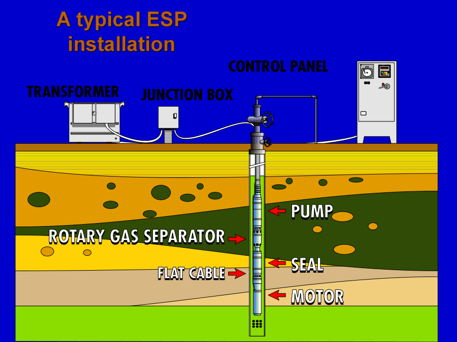
1、nThe Monitoring System(optional)nThe Power CablenThe MotorThe Seal SectionnThe PumpBuilt in Discharge headTubing screws in hereBolts to the SealPump ShaftBuilt in IntakePump HousingRotating ImpellerStationary Diffuser The PumpLT=Lower Tandem pump(with built in intake)The seal bolts on hereLT/MT=Lowe
2、r/Middle Tandem pumpHeadShipping CapIf MT(middle tandem)or LT(Lower Tandem)then a flange face is the head of the pump.If Upper Tandem(UT)then a discharge is built into the pump.UT PumpBuilt in Discharge headMiddle Tandem pump BaseUT or MT pumpShipping CapThe Bolt on HeadThe Middle Tandem or Lower Ta
3、ndem Pump HeadGas separator intake(cut away).May be bolted on to the base of a MT(Middle Tandem)or UT(Upper Tandem)PumpThe Seal bolts on here.UT or MT pump bolts on here.Stages stacked on a shaft and compressed in a housing.Centrilift Submersible PumpRotating(right to left)impellersStationary diffus
4、ersCutaway of PumpImpellerMixed Flow-flow path has both axial and radial direction with respect to the pump shaftRadial Flow-flow path is generally perpendicular(radial)with respect to the pump shaftImpeller HubBottom ShroudTop ShroudImpeller SkirtImpeller EyeImpeller VaneDownthrust WasherUpthrust W
5、asherImpellerEyeHubUpper ShroudVanesLower ShroudSkirtImpellerThe impeller rotates about the pump axis,with the shaftIt provides the centrifugal force to the fluid-gives it energy.ImpellerFluid enters the impeller through the eye near the shaft and exits the impeller on the outside.Impeller-Cut AwayD
6、iffuserDiffuserThe diffuser does not rotate,it turns the fluid up into the next impeller It transforms the fluid velocity,its energy,into headDiffuser-Cut AwayImpeller&DiffuserDiffuser directs fluid into the eye of the impellerImpeller spins and gives energy to fluid which exits around the outsideDi
7、ffuser redirects the fluid up into the next impeller and turns fluid energy into headImpeller in Diffuser-A Pump StagePump Stage -cut awayFlow,Barrels per day(BPD)Operating RangeHead CapacityPump EfficiencyBrake Horse PowerHead in FeetBHPPump Curve80604020123Efficiency%Best Efficiency Point(BEP)Tubi
8、ng PressurePump StageFluid ReservoirDeveloping the Pump Stage Head Capacity CurveFluid ReservoirHead(Lift)1Developing the Pump Stage Head Capacity CurveHead in FeetSingle stage performance for a given RPM and fluid viscosityPump Stage Characteristics01020304050601Flow,Barrels per day(BPD)02004006008
9、001000Developing the Pump Stage Head Capacity CurveFluid ReservoirHead1Developing the Pump Stage Head Capacity CurveHead Flow12Fluid ReservoirDeveloping the Pump Stage Head Capacity CurveHead in FeetPump Stage Characteristics0102030405060Flow,Barrels per day(BPD)0200400600800100012Developing the Pum
10、p Stage Head Capacity CurveHead Flow12Fluid ReservoirDeveloping the Pump Stage Head Capacity CurveHead Flow123Fluid ReservoirDeveloping the Pump Stage Head Capacity CurveHead in FeetPump Stage Characteristics0102030405060Flow,Barrels per day(BPD)02004006008001000123Developing the Pump Stage-Head/Cap
11、acity CurveHead in FeetPump Curve0102030405060Flow,Barrels per day(BPD)02004006008001000Developing the Pump Stage-Head/Capacity Curve280 Ft 600 bpdFluid ReservoirUsing the Pump Curve to size a pumpHead in FeetPump Curve0102030405060Flow,Barrels per day(BPD)0200400600800100040 feet/stage 600 BPD56 fe
12、et/stage 0 BPDUsing the Pump Curve to size a pump280 Ft 600 bpdFluid ReservoirUsing the Pump Curve to size a pump280 Ft 600 bpdFluid Reservoir56 feet 0 BPDFor 600 BPDStages=280/40=7Using the Pump Curve to size a pump280 Ft 600 bpdFluid ReservoirUsing the Pump Curve to size a pump280 Ft 600 bpdFluid
13、ReservoirUsing the Pump Curve to size a pumpMultiple StagesThe head that one stage develops is multiplied by the number of stages to determine the total head a pump will deliver.At a given flow rate!600 bpd40 ft80 ft40 ft136000)(SpgrBPDFeetPHydraulicHBHPPHydraulicHEfficiency GC3500Single Stage Perfo
14、rmance,3500 RPM SpGr=1.0,60 Hertz 4000 BPD,42 ft/stg,1.8 HP/stg,70%efficientStagesStagesStageLiftTDH119425000/214)00.1)(80.1(119)(SpGrStagesPumpHPStageBHPSo we need a motor bigger than 214HP,say 255HP.It is free to move up and down on the pump shaftPump Thrust LoadPump Thrust LoadPump Thrust LoadPum
15、p Thrust LoadThis causes the impeller to be moved down This is a positive downward force termed DownthrustPump Thrust LoadThis causes the impeller to be moved up Pump Thrust LoadThe downward force is now reversed(negative),it is termed UpthrustThis causes the impeller to be moved up Pump Thrust Load
16、This increases the UpthrustThis causes the impeller to be held up Flow from DiffuserImpeller Flow PathFluid velocity&viscousdrag forces add to upthrust.Pressure generated bythe stageShaft thrust is the result of the pumpdischarge pressure acting on the crosssectional end of the pump shaft The two th
17、ings that determine shaftthrust is the pump discharge pressure(or TDH)and the diameter of the pumpshaft.This thrust is transmitted directlyto the seal section thrust bearingThe pump is designed to operate in slight to moderate Downthrust.Downthrust washers Upthrust washerPump Thrust LoadDownthrust W
18、asherHub WasherEye WasherUpthrust WasherImpeller-TopImpeller-BottomHubUpper ShroudVaneLower ShroudSkirtEyeUpthrust WasherDown thrust WasherImpeller-Name the parts:Flow,Barrels per day(BPD)Operating RangeHead CapacityPump EfficiencyBrake Horse PowerHead in FeetBHPPump Curve80604020123Efficiency%Best
19、Efficiency Point(BEP)Operating RangeGC2200 Single Stage Performance RPM 60Hz=3500(Sg=1)Operating RangeGC2200 Single Stage Performance RPM 60Hz=3500(Sg=1)Fluid ReservoirNormal RPMFluid ReservoirFluid ReservoirNormal RPMSlower RPMFluid ReservoirFluid ReservoirFluid ReservoirNormal RPMSlower RPMFaster
20、RPM“Affinity Laws”60Hz Operating RangeMin flow =1500bpd 54ftBEP flow=2200bpd 46ftMax flow=3000bpd 25ftMin flow =2000bpd 96ftBEP flow=2933bpd 82ftMax flow=4000bpd 44ft80Hz Operating Range?Tornado CurveMin FlowBEP FlowMax FlowMotorPumpMotorPumpMotorPumpMotorSealPumpCentriliftLocated between the pump a
21、nd motorTransfers the motor torque to the pump shaftLabyrinth ChamberLabyrinth ChamberDouble Labyrinth ChamberPumpMotorLabyrinth ChamberPumpMotorBag or BladderPumpMotorLabyrinth ChamberMotor Oil-HeatedLabyrinth ChamberMotor Oil-CoolingDouble Labyrinth ChamberMotorBag(or Bladder)MotorMotor Oil-Heated
22、Bag(or Bladder)MotorMotor Oil-HeatedBag(or Bladder)MotorMotor Oil-HeatedCheck valveBag(or Bladder)MotorMotor Oil-HeatedCheck valveBag(or Bladder)MotorMotor Oil-HeatedCheck valveBag(or Bladder)MotorMotor Oil-HeatedCheck valveMotorMotor Oil-CoolingMotorMotor Oil-CoolingMotorMotor Oil-HeatedDouble Bags
23、MotorMotor Oil-HeatedDouble BagsMotorMotor Oil-HeatedDouble BagsMotorMotor Oil-HeatedParallel BagsMotorMotor Oil-HeatedParallel BagsMotorn thousand feetCompression,Fixed Impeller,PumpsCompression,Fixed Impeller,PumpsMotorSealPumpSeal(Lower Chamber)MotorHeat Exchange AreaThrust Bearing AreaSeal(Lower
24、 Chamber)MotorThrust RunnerThrust Runner Carbon FaceBearingBearing RetainerScreen FilterUpthrust RingSeal Unit BaseBearing RetainerOil PumpBearingCarbon FaceThrust RunnerThrust Runner Carbon FaceThrust RunnerUpthrust BearingUpthrust BearingBearing RunnerBearing Assembly CompleteStator LaminationsKap
25、ton-Wrapped Magnet WireRotorBearing with T-ringHousingEpoxy EncapsulationrotorBearing with T-RingStatorStator Laminations on a MandrelStator Laminations pressed into the motor housingA wound Stator with Leads attachedRotor Copper End RingRotor LaminationsRotor BearingRotor T ringRotor SpacersRotor B
26、earingRotorSPH p496060HZNPHPNPHPHZ6060HZNPVNPVHZ60NPANPAHZ6060HZNPHPNPHPHZHZBHPNPHPHZ6060Substitute the pump BHPHZ at the maximum design HZ for the NPHPHZ and solve for NPHP60 2 4 3 1 3 24 1 1 2 35 412453 2 5 43 1 Standard Power CableCapillary TubesCapillary Tube3 KV4 KV5 KVHead vs.Flow,Variable Speed(30-90 Hz),
- 温馨提示:
1: 本站所有资源如无特殊说明,都需要本地电脑安装OFFICE2007和PDF阅读器。图纸软件为CAD,CAXA,PROE,UG,SolidWorks等.压缩文件请下载最新的WinRAR软件解压。
2: 本站的文档不包含任何第三方提供的附件图纸等,如果需要附件,请联系上传者。文件的所有权益归上传用户所有。
3.本站RAR压缩包中若带图纸,网页内容里面会有图纸预览,若没有图纸预览就没有图纸。
4. 未经权益所有人同意不得将文件中的内容挪作商业或盈利用途。
5. 装配图网仅提供信息存储空间,仅对用户上传内容的表现方式做保护处理,对用户上传分享的文档内容本身不做任何修改或编辑,并不能对任何下载内容负责。
6. 下载文件中如有侵权或不适当内容,请与我们联系,我们立即纠正。
7. 本站不保证下载资源的准确性、安全性和完整性, 同时也不承担用户因使用这些下载资源对自己和他人造成任何形式的伤害或损失。
