 矿山装载机动臂开裂的计算与实验分析外文文献翻译@中英文翻译@外文翻译

《矿山装载机动臂开裂的计算与实验分析外文文献翻译@中英文翻译@外文翻译》由会员分享,可在线阅读,更多相关《矿山装载机动臂开裂的计算与实验分析外文文献翻译@中英文翻译@外文翻译(23页珍藏版)》请在装配图网上搜索。
1、附录:译文及原文 矿山装载机动臂开裂的计算与实验分析 Rusiski, J. Czmochowski, P. Moczko 弗罗茨瓦夫理工大学机械设计和操作研究院,Lukasiewicza 6/7 51-370 弗罗茨瓦夫,波兰 通讯作者邮件地址:eugeniusz.rusinskipwr.wroc.pl 收录时间 15.03.2006,接受修订的时间为 2006 年 4 月 30 日。 分析和建模 摘要: 目的:本文的主要目的是考论挖机在井下工作设计的问题与研究地下矿机在工作时的开裂原因 设计 /方法 /方式:主要采用了数值模拟和实验的方法。采用有限元法用于数值模拟。对材料的评价 运用了断口
2、微观评价,化学分析,硬度实验的方法。其实现的方法是通过破解装载机动臂,标本材 料的评价和两者共同对比的结果的数值模拟分析得出。结果是主要通过数值实验、离散起重臂和预 定义边界条件的模型来确定的。对于起重臂的有限元分析对应力分布的极端负载条件提供了信息。 这项研究包括采用显微镜做宏观和断口检查,起重臂材料的硬度试验 。然后从两种方法得出结论。 调查结果:发现地下铜矿用装载机起重臂损坏的原因。 实践意义:本研究为理论设计和制造工艺之间的过程中,在设计到对象的过程提供了广泛的观点方 法。 独创 性 /价 值 : 本 文 用 评估 和测 试 结 果 的信 息 , 解 释 说明 的 动 臂 断 裂 的
3、原 因 的 关系 。 实 验 和 数 值 分 析 显示设计和机器的制造过程的关系。这可以为设计师和研究员在调查过程或如何防止同类机器的故 障时提供有力的帮助。 关键字: CAD/CAM;材料;金属学; 介绍 地下采矿机械包括以下:井架,屋顶,抽苔机,装载机,运输车辆以及其它一般用于矿石开采,装 载和 运 输 的 设 备 ( 即 最 为 基本 挖 掘 任 务 的 设 备 ) 1。 在 生 产 实 践 中 探 索 与 试 验证 明 地 下 工 作 的 设 备 以及作为其子组件的要求与地表运行的机器不同。通常情况下开采条件更为苛刻。由于他们的特点 的使 用 过 程 , 他 们 所 受 到 差的 工
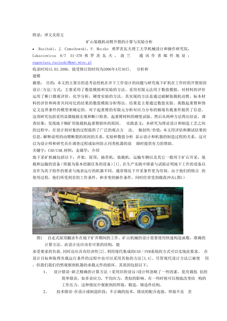
4、作 条 件 , 和 多 变 的 操作 条 件 , 同 时 经 常 受 到 载荷 冲 击 。(图 1) 图 1 自走式屋顶翻录车在地下矿井期间的工作。 矿山机械的设计需要使用快速构造函数,准确的计算方法。此设计还应该有可靠的结构,能 承受 要 求 的 负 荷 , 同 时还 应具 有 经 济 性 2。 利 用 现 代集 成 的 CAD / FEM 系 统的 方式 可 以 实 现 此 要 求 。 在设计 目标和取得负载运行条件的过程中也可以采用其他的方法 3,4。尽管现代设计方法已被使 用,但我们我们仍然观察到机器的承载元件的损坏。其原因包括以下: 1、 设计错误 -缺乏精确的计算方法(采用旧的设计
5、 ), 设 计师忽略了一些因素,犯负载低 估的简单错误,如多余应力,平均应力,类似的影响。在一些时候可以彻底改变结 构的工作压力。这种情况中观察到的焊接,锻造,铸造件结构。 2、 技术错误 -在设计或制造阶段:不正确的技术,错误的配合连接,焊接不良 差质量的焊接技术,材料缺陷如不正确的钢种,材料在张拉层压的连接。 3、 开采错误 -开采过程中过载所造成的或不可预知的环境下出现的机械故障。 通过精确的分析可以更好的了解开采过程中损坏故障的情况与原因,从而改善未来设计的对象。 在广大的地下操作机器中,我们着重考虑装载机。这种类型的机器常见的故障是铲斗和切割刀片损 坏。还有就是构架和载臂相关的损坏。
6、在地下采铜矿机械中,起重臂常常受到损坏,图 2 所示。里 面包括起重臂的截面断裂,导致完全从机器的前部与余部分的悬臂的分离。此故障常发生在铲斗的 过载运行。 图 2 损坏的载铲 在本设计中为了以确定的吊杆损伤,判断其原因,采用 CAD / FEM 对起重臂的数值应力进行评估。 此外,还进行详细的材料分析,以检查可能的物质和技术故障,这也可能是 造成这种损伤的原因。 数值试验 起重臂的几何模型是用来创建一个离散模型。采用有限元法 6, 7 和 8 进行数字假设: 1、使用 shell元素的钣金建模 2、使用连接器,执行器,车轴和螺栓 /引脚建模修改 横梁 的元素, 3、使用 RBE3 类型的元素
7、承载节点建模 4、铲斗模型采用硬类型元素 起重臂的数字建模如图 3 所示。 图 3 起重机的吊臂的离散模型 根据装载机的 技术参数的分析设定了起重臂的四个位置。其中一个假设如图 4 所示。采用了 18 种方 法 进 行 分 析 。 每 个 这 些假 定 的 铲 斗 的 一 个 固 定 位置 , 承 受 致 动 器 所 产 生 的应 力 负 荷 。 作 为 简 化, 假设铲斗有一个非常坚固的结构,以同样的假设作为它的自己旋转轴 9。 图 4 副臂的位置图和负荷图 对于起重臂的应力计算采用了 I -DEAS 10系统的有限元分析。样品的应力计算如图 5 所示 图 5 根据胡伯 -米塞斯理论采用等高
8、线表示臂的应力水平 计算出来的三维图显示了起重臂应力的压力大小和形变,主要取决于上的载荷的大 小和几 何 结 构。这实例的具有代表性。在这种情况下最大组合应力 压力主要集中在造成铲斗结构缺口处的驱动器的接点上。在这个接点上,同时也有一个改变起重臂 的侧带材的刚性引起的衬套的致动机构的安装螺栓上。这也是那里的起重臂开裂发起点。 3.材料评估 损坏的起重臂和它是由材料使用以下方法评估11: 1、 肉眼目视检查,以及体视显微镜检查使用放大倍数可达 30 倍。 2、 采用扫描电子显微镜,进行断口评价。 3、 化学分析 4、 微观评价 5、 硬度测试 3.1 宏观的断口评价 对骨折运行起重臂的整个横 截
9、面进行臂的测试(图 6) 根据断口的分析可以得出该骨折是脆性断裂,如图( 6)所标记的 A 和 B 点所位于 S1 焊缝熔合 材料的杆。分析该断裂点的表面形貌 A 和 B 用扫描电子显微镜显示出平滑的表面,其特征是对骨折 始发点。在点 A 和 B 的断裂可能起源已在或焊后不久,最终导致立即脆性吊臂断裂。它也可能焊接 骨折导致小区域的疲劳。在 A 点所观察到表面形态如图 7 所示。 执行了焊接接头的宏观评价的 S2 角焊缝交叉显微如图 8 所示。焊缝表面可用阿德勒的蚀刻液 ( Ma11Fe )蚀刻。 图 6 断裂带形态 图 7 为图 6 中 A 点表面形态的 SEM 图像 观察证明不完整的角焊缝
10、在焊接熔深的底部。这两种焊接以及焊缝熔合线中还存在着许多焊接 错误而产生的气泡。焊缝的宏观检查 关节也透露,在扁棒,起重臂各种结构和 焊接接头材料以及焊接热影响区(热影响区)内。焊缝关节的宏观检查透漏出扁棒,起重臂各种结 构和焊接接头材料以及焊接在热影响区(热影响区)内。 图 8 扁钢和起重臂之间的焊接接头 3.2 微观评价 对于焊接接头的连接点微观评测优于宏观评价。 在 Mi1Fe 蚀刻后得出结论为 起重臂焊接接头的外部材料的微观结构是的 ferriticperlite 结构, 存在 轻微 的 Widmannsttten 特 性 结 构 ( 图 9)。 在 这种 类 型 材 料 的 化 学
11、成 的 结构 导 致 了 削 弱 力 学 参 数的,并且还引起焊接的不均匀。焊缝区的贝氏体的地方出现珍珠岩状(伪共)结构。该焊接点的 伪共结构表明,焊接是使用中碳钢焊条进行焊接的。 热影响区表现出中小板珍珠岩结构以及马氏体结构,其中热影响区是区硬化的,从而导致形成 脆性 裂 纹 。 当 比 较 起 重 臂材 料和 热 影 响 区 时 在 起重 臂 HAZ 和 焊 接 接 头 的 铁 素体 - 珠 光 体 结 构 之 间的 的珍珠 岩结构存在明显差异。这种快速变化的结构导致焊接材料和焊接接头的连接的参数在显著变 化。这也表明,这是使用不当焊条进行焊接时,具有与本焊接材料显著不同的组合物。焊缝,热
12、影 响区的微观结构和焊接误差如图 10 所示。 9 起重臂材料的微观结构 图 10 焊缝的显微组织 - 热影响区和焊缝 3.3 硬度测试 根据波兰标准 PN- EN 1043-1 采用维氏的方法检测硬度。该测试显示,热影响区在焊接接头显 著硬化与起重臂材料与材料的局部淬火,从而导致发生脆性断裂。 4 结论 本文的主要目的是讨论设 计地下采矿用机械的问题,并在其基础上分析了挖掘机杆的断裂问题 的原因,和它表面遭受损害如图 2 所示。数值和实验方法的使用,是从更广泛的角度 看发生在这种类型的机器的这样的事故。 基于 所 执 行 的 热 潮 材 料 测 试 , 分 析 了 与 润 滑 槽 的扁 钢之
13、 间 的 断裂 , 焊 接 接头 以及 起 重 臂 侧 的 片, 以及在 MES 应力分析,发现了: 1、 使用 Mi1Fe 片 段 的 显 微 镜评 价 蚀 刻 , 证 明 了 焊缝 的外 起 重 臂 的 材 料 已 经 呈 现出 轻 微 的 证 据 铁 素体 - 珠光体结构出现了 Widmannsttten 结构特征。这种结构由于热处理不当和锻造,意味着, 用于起重 臂的金属是不充分轧并具有较低的机械强度。 2、根据波兰 PN-86/H-84018 的标准,碳当量计算,基于该钢在测试过程中确定的化学组成,在 0.453 和接近到 0.46 的容许值之间。然而,评价表明吊臂景气钢可焊性较差,
14、应考虑到进行 任意的焊接修理前的说明。 3、 为 各 种 各 样 负 载 的 进 行 了有 限 元 分 析 证 明 了 脆 性 断裂 发 生 在 一 个 结 构 缺 口 , 造 成 应 力 集 中在 一点。在起重臂经受例合并应力达到最大,扭转力为 4、 可以 得 出 结 论 , 没 有 直 接 的焊 接 信 息 进 行 ( 这 只 能 是通 过 实 验 室 材 料 分 析 获 得 ) 确定 : Widmannsttten 结构的存在 CE 边缘碳当量值 造成 额 外 引 入 的 残 余 和 局 部应 力 改 变 材 料 特 性 ( 材 料硬 化 )。 这 反 过来 加 速脆 性断 裂 的 发
15、生。 5、 因为材料的缺陷与结构不合理所造成起重臂断裂是不可避免的,装载机起重臂 负荷运行,限制了其使用期。 参考文献 1 K. Pieczonka: Scoop Loaders (in Polish), Wroclaw University of Technology Publishing House, Wroclaw 1988. 2 T. Smolnicki, E. Rusinski, J. Czmochowski: Some aspects of load carying structures of mining machines, Mechanical Review, 1/2004 p
16、. 32. 3 G. Wszolek: Vibration analysis of the excavator model in GRAFSIM program on the basis of a block diagram method. Journal of Materials Processing Technology 157/158 (2004) 268-273 4 A. Buchacz, A. Machura, M. Pasek, Hypergraphsinmodelling and analysis of complex mechanical systems, Systems An
17、alysis Modelling Simulation, (2003), Taylor & Francis, New York. 5 A. Krukowski, J. Tutaj: Deformational connections. National Scientific publications, 1987. 6 E. Rusinski, J. Czmochowski, T. Smolnicki: Advanced Finite Element Method for Load-carrying Structures of Machines (in Polish), Wroclaw Univ
18、ersity of Technology Publishing House, Wroclaw 2000. 7 E. Rusinski: Finite Element Method; System COSMOS/M” (in Polish), WKL, Warsaw 1994 8 O.C. Zienkiewicz, R.L. Taylor: The finite element method. Vol. 1, Vol. 2. McGraw-Hill Bool Company, London 1991 9 E. Rusinski, K. Kanczewski, P. Moczko, W. Dudz
19、inski, M. Lachowicz: Determination of causes of fracture of loader jib boom LK-2NCC. Report No. S-019/2005, Institute of Machine Design and Operation at the Wroclaw University of Technology. 10 Structural Dynamic Research Corporation: Exploring IDEAS Design. 11 W. Dudzinski and others: Structural ma
20、terials in machines design, Wroclaw University of Technology Publishing House, Wroclaw 1994. 30 of Achievements in Materials and Manufacturing Engineering VOLUME 17 ISSUE 1-2 July-August 2006 Numerical and experimental analysis of a mines loader boom crack E. Rusioski*, J. Czmochowski, P. Moczko Ins
21、titute of Machines Design and Operation, Wr oclaw University of Technology, ul. Lukasiewicza 7/9 51-370 Wroclaw, Poland * Corresponding author: E-mail address: eugeniusz.rusinskipwr.wroc.pl Received 15.03.2006; accepted in revised form 30.04.2006 AbstrAct Purpose: The main purposes of the paper are
22、to discuss designing problems of machines used in underground mining and investigation of its reasons based on cracked boom of underground mine machine. Design/methodology/approach: Numerical and experimental approach was considered. The finite element method was used for numerical simulation. Fract
23、ographic and microscopic evaluation, chemical analysis, hardness tests were used to perform material evaluations. The objectives are achieved by numerical simulation of cracked loader boom, material evaluations of specimens and comparison of results achieved from both approaches. These were determin
24、ed through a numerical experiment, based on a discrete model of the jib boom and predefined boundary conditions. The finite element analysis for the jib boom provided information about stress distribution for extreme load conditions. The study included macroscopic and fractographic inspection, micro
25、scopic evaluation as well as hardness tests of the material used for the jib boom. Conclusions from both approaches were drawn then. Findings: The causes of damage of a loader jib boom used at an underground copper mine were found. Practical implications: The study provides practical implication int
26、o designing process of mentioned objects by wider view of relationships between theoretical design and manufacturing process. O riginality/value: The paper provides information backed by evaluation and test results, stating the nexus of causes of the boom failure. The experimental and numerical appr
27、oaches show relationship between designing and manufacturing process of machines. This can be helpful for the designers and researchers looking for reasons, methods of investigations or how to prevent failures of similar machines. Keywords: CAD/CAM; Materials; Metallography Analysis and modelling 31
28、 1. Introduction Short paper 273 Machines used in underground mining, such as: derricks, roof bolting machines, loaders, transportation vehicles as well as others are generally used for ore exploitation, loading and transportation, i.e. basic mining tasks 1. Construction design practice, exploitatio
29、n and tests prove that such machines as well as their sub-components are subject to requirements radically different from machines operating on the surface. In general exploitations conditions are much heavier. Considering their specific application, they are subject to adverse operating conditions,
30、 variable operating conditions and are often subject to percussive loads (fig. 1). Fig. 1. SWB (Self-propelled roof ripping vehicles) during operation at an underground mine Design of mining machines requires from the constructor to use quick and accurate calculation methods. The design should Copyr
31、ight by International OCSCO World Press. All rights reserved. 2006 1. Introduction 32 result in a reliable construction, withstanding the required loads, whilst also being economical 2. This can be achieved through the use of modern integrated CAD/FEM systems. Other approaches can be also used for t
32、he designing purpose and in order to achieve loads coming from operational conditions 3, 4. Even though modern design methods are already employed, we still observe damage of load bearing elements of machines. Some of the reasons for this include: design errors lack of precise calculation methods (o
33、lder construction), load underestimate, simple mistakes made by designer, neglecting influence of some factors such as residual stresses, mean stress, fits influence 5, which in certain circumstances can drastically change stress effort of structures. This situation is observed in welded structures,
34、 forged and cast parts, technological errors during the design or production stage: incorrect technology, wrong fits in connection, bad welds quality and wrong welding technology, material faults incorrect steel grade, lamination of material in tensioned connections, exploitation errors overloads ca
35、used by improper exploitation or by unpredicted circumstances, exploitation with mechanical failures. A precise analysis of damage occurring during exploitation allows for better understanding of circumstances and causes of faults, thus allowing for improvement of design of future objects. Among the
36、 vast number of machines operating in underground mines, we would like to concentrate on loaders. A common fault, which is found in machines of this type is damage to the scoop bucket and the cutting blade. There are also cases related to damage of the frame or the loading jib. During exploitation o
37、f one of such machines in an underground copper mine, the jib suffered damage as shown in fig. 2. This consisted of a cross fracture of the jib boom, causing complete separation of the front part of the jib from the rest of the machine. The fault occurred during unloading of the scoop. Fig. 2. Damag
38、ed loader boom In order to determine the causes of the jib damage, a decision was made to verify the design of the machine, using CAD/FEM numerical stress assessment of the jib boom. Furthermore, detailed material analysis was also performed, to check for possible material and technological faults,
39、which could also be plausible causes of this damage. Journal of Achievements in Materials and Manufacturing Engineering Volume 17 Issue 1-2 July-August 2006 33 2. Numerical experiment The geometrical model of the jib boom was used to create a discrete model. Digitization was performed using the fini
40、te element method 6, 7 and 8 assuming: 1. modeling of sheet metal using Shell elements, 2. modeling of connectors, actuators, axles and bolts / pins using modified Beam elements, 3. modeling of bearing nodes using RBE3 type elements, 4. modeling of the scoop bucket and the boom using Rigid type elem
41、ents. The digital model of the jib boom is shown in fig. 3. Fig. 3. Discrete model of the jib arm According to technical parameters of the loader the analysis assumed four positions of the jib boom. One of assumed position is shown in fig. 4. Stress analysis was performed for 18 different cases. Eac
42、h of these assumed a fixed position of the scoop bucket, with the stress load being generated by the actuators. A simplifications was made, assuming the scoop bucket as an ideally rigid construction, similarly a same assumption was made for its rotation axis 9. Fig. 4. Diagram of jib boom positions
43、and loads The stress calculations for the jib boom were performed using finite element analysis using the I-DEAS 10 system. Sample stress calculations are presented in fig. 5. 274 Short paper 3 Rusioski, J. Czmochowski, P. Moczko 2. Numerical experiment 34 3. Material evaluation 3.1. Macroscopic and
44、 fractographic evaluation Analysis and modelling aterial ev luation 3.1. Macroscopic and fractographic evaluation Fig. 5. Contour lines representing stress levels in the boom, according to the Huber-Mises theory The computations provided a 3D representation of the stress levels as well as show the d
45、eflection of the jib boom, depending on the load size and geometrical configuration. The most representative case was determined. The maximum combined stresses in this case are: MAX = 413 MPa Stress concentration is caused at a structural notch at the booms actuator mounting point. At this point the
46、re is also a change in the rigidity of the booms side strip caused by the bushing for the actuator mechanisms mounting bolt. This is also the point where the boom cracking was initiated. The damaged jib boom as well the materials it is made of were evaluated using the following methods 11: 3.2. macr
47、oscopic visual inspection as well as stereomicroscope inspection using magnifications up to 30 x, 3.3. fractographic evaluation - scanning electron microscope, 3.4. chemical analysis, 3.5. microscopic evaluation, 3.6. hardness tests. The boom supplied for testing had a fracture running across the en
48、tire cross section of the boom (fig. 6). The fractographic analysis concluded that the fracture was an immediate brittle fracture, originating at points marked A and B in fig. 6, located along the S1 weld joint fusion with the boom material. Analyzing the surface topography of the fracture points A
49、and B using a scanning electron microscope showed a smoothed surface, which is characteristic for fracture origination points. The fractures at points A and B probably originated already during or shortly after welding, and ultimately lead to an immediate brittle fracture of the jib boom. It is also
50、 probable that the welding fractures lead to a small fatigue zone. Surface morphology observed at point A is shown in fig. 7. Macroscopic evaluation of the weld joint was performed at the cross microsection of the S2 fillet weld (fig. 8). The weld surface was etched using Adlers etching solution (Ma
51、11Fe). 35 3.2. Microscopic evaluation 275 Fig. 6. Topography of the fracture zone Fig.7. Surface morphology at point A - fig.6. SEM image Observations proved incomplete weld penetration at the root of the fillet weld. Both welds as well as the weld fusion line also exhibited numerous welding errors
52、in the form of interruptions as well as gas bubbles. The macrostructure examination of the weld joint also revealed various structures in the flat bar, jib boom and weld joint materials as well as within the HAZ (heat affected zone). Fig. 8. Weld joint between the flat bar and jib boom Microscopic e
53、valuation Microscopic evaluation was performed for the cross microsection of the weld joint, which was earlier subject of the macroscopic evaluation. After etching with Mi1Fe it was concluded that the jib boom material microstructure outside of the weld joint is a ferritic- perlite structure exhibit
54、ing slight characteristics of a Widmannsttten structure (fig. 9). This type of structure results in weakening of the mechanical parameters and also causes problems during welding, because of the non-homogeneous chemical composition of the material. The weld area has a perlite (pseudoeutectoid) struc
55、ture with local occurrences of bainite. The pseudoeutectoid structure of the joint suggests that welding was performed using a medium carbon welding rod. The heat-affected zone exhibits small plate perlite structures as well as areas of martensite structure, where the HAZ was hardened, thus leading
56、to formation of brittle cracks. When comparing the jib boom material and the HAZ there is a clear difference between the ferritic-perlite structure of the jib boom and the perlite structure of the HAZ and weld joint. This rapid change of structure leads to significant change of parameters at the con
57、nection of the welded material and weld joint. It suggests Numerical and experimental analysis of a mines loader boom crack 36 4. Conclusions 3.3. Hardness testing c nclusions also, that the weld was performed using an improper welding rod, having a significantly different composition as compared to
58、 the welded materials. The microstructure of the weld joint, HAZ and the welding errors are shown in fig. 10. Fig. 9. Microstructure of the jib boom material Fig. 10. Microstructure of the weld - HAZ and weld joint Hardness testing Hardness was checked using the Vickers method, using single impressi
59、ons according to the Polish standard PN-EN 1043-1. The tests showed significant hardening of the HAZ at the weld joint with the jib boom material with local hardening of the material, which lead to occurrence of the brittle fractures. The main purposes of the paper were to discuss designing problems
60、 of machines used in underground mining and investigation of its reasons based on cracked boom of mining machine, which suffered damage as shown in fig. 2. Numerical and experimental approaches were used in order to achieve wider point of view of such accidents, which happens in this type of machine
61、s. Based on the performed boom material tests, evaluation of the fracture, weld joint between the flat bar with the lubrication groove and the jib boom side strip as well as the MES stress analysis, it was found that: The microscopic evaluation of fragments etched using Mi1Fe, proved that the materi
62、al of the jib boom outside of the weld has a ferritic-perlite structure showing slight evidence of Widmannsttten structure characteristics. This structure resulted from improper heat treatment and forging, meaning that the metal used for the jib boom was insufficiently rolled and thus has lower mech
63、anical strength. It also makes welding of this material difficult. Calculation of the carbon equivalent according to the Polish standard PN-86/H-84018, based on the chemical composition Journal of Achievements in Materials and Manufacturing Engineering Volume 17 Issue 1-2 July-August 2006 37 Referen
64、ces of this steel determined during testing, is 0,453 % and is close to the allowable value of 0,46 %. However, the evaluated jib boom steel has poor weldability, which should be taken into account before performing any welding repairs; CE = C + Mn/6 + (Cr+Mo+V)/5 + (Ni+Cu)/15 = 0,22 + 1,40/6 = 0,45
65、3 % 0,46 % The finite element analysis performed for a wide variety of loads proved that the brittle fracture occurred at a structural notch, causing concentration of stress forces. The maximum combined stresses in cases where the jib boom was subjected to torsion forces amounted to:MAX = 336 413 MP
66、a. It was concluded that welding performed without information (which could only have been obtain through laboratory material analysis) about: E. presence of Widmannsttten structures F. borderline CE Carbon equivalent value G. caused introduction of additional residual stress and local change in mat
67、erial characteristics (material hardening). This in turn accelerated the occurrence of brittle fracture. The jib boom fracture was inevitable, because the material is defective and has an improper structure. The loader jib boom thus has limited fatigue life. 1 K. Pieczonka: Scoop Loaders (in Polish)
68、, Wroclaw University of Technology Publishing House, Wroclaw 1988. 2 T. Smolnicki, E. Rusinski, J. Czmochowski: Some aspects of load carying structures of mining machines, Mechanical Review, 1/2004 p. 32. 3 G. Wszolek: Vibration analysis of the excavator model in GRAFSIM program on the basis of a bl
69、ock diagram method. Journal of Materials Processing Technology 157/158 (2004) 268-273 4 A. Buchacz, A. Machura, M. Pasek, Hypergraphs in modelling and analysis of complex mechanical systems, Systems Analysis Modelling Simulation, (2003), Taylor & Francis, New York. 5 A. Krukowski, J. Tutaj: Deformat
70、ional connections. National Scientific publications, 1987. 6 E. Rusinski, J. Czmochowski, T. Smolnicki: Advanced Finite Element Method for Load-carrying Structures of Machines (in Polish), Wroclaw University of Technology Publishing House, Wroclaw 2000. 7 E. Rusinski: Finite Element Method; System C
71、OSMOS/M” (in Polish), WK, Warsaw 1994 8 O.C. Zienkiewicz, R.L. Taylor: The finite element method. Vol. 1, Vol. 2. McGraw-Hill Bool Company, London 1991. 9 E. Rusinski, K. Kanczewski, P. Moczko, W. Dudzinski, M. Lachowicz: Determination of causes of fracture of loader jib boom K-2NCC. Report No. S-01
72、9/2005, Institute of Machine Design and Operation at the Wroclaw University of Technology. 10 Structural Dynamic Research Corporation: Exploring I- DEAS Design. 11 W. Dudzinski and others: Structural materials in machines design, Wroclaw University of Technology Publishing House, Wroclaw 1994. references 38 276 39 Short paper 40 READING DIRECT: www.journalamme.org
- 温馨提示:
1: 本站所有资源如无特殊说明,都需要本地电脑安装OFFICE2007和PDF阅读器。图纸软件为CAD,CAXA,PROE,UG,SolidWorks等.压缩文件请下载最新的WinRAR软件解压。
2: 本站的文档不包含任何第三方提供的附件图纸等,如果需要附件,请联系上传者。文件的所有权益归上传用户所有。
3.本站RAR压缩包中若带图纸,网页内容里面会有图纸预览,若没有图纸预览就没有图纸。
4. 未经权益所有人同意不得将文件中的内容挪作商业或盈利用途。
5. 装配图网仅提供信息存储空间,仅对用户上传内容的表现方式做保护处理,对用户上传分享的文档内容本身不做任何修改或编辑,并不能对任何下载内容负责。
6. 下载文件中如有侵权或不适当内容,请与我们联系,我们立即纠正。
7. 本站不保证下载资源的准确性、安全性和完整性, 同时也不承担用户因使用这些下载资源对自己和他人造成任何形式的伤害或损失。
