 思科模拟器试验步骤

《思科模拟器试验步骤》由会员分享,可在线阅读,更多相关《思科模拟器试验步骤(33页珍藏版)》请在装配图网上搜索。
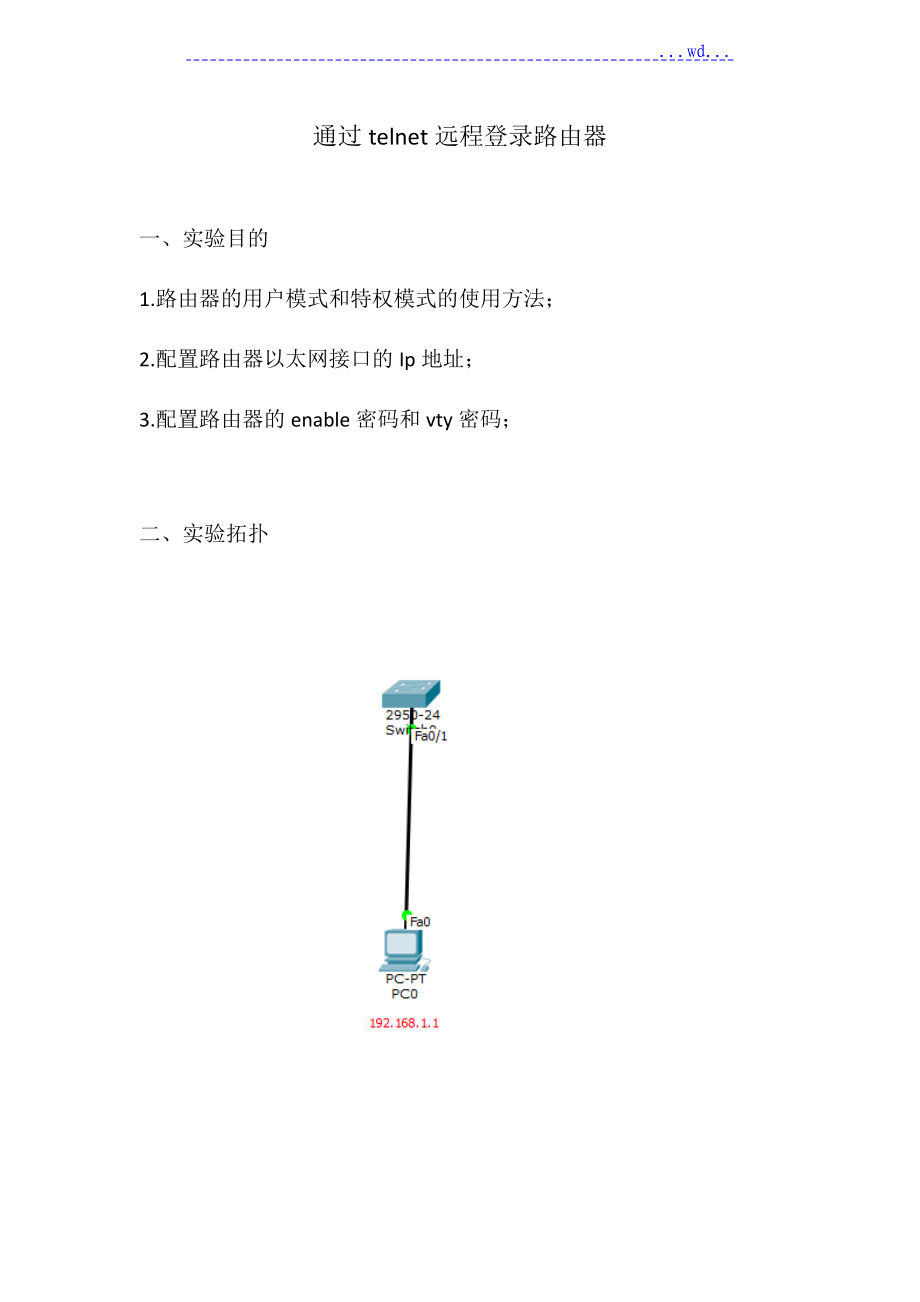
1、 .wd.通过telnet远程登录路由器一、实验目的1. 路由器的用户模式和特权模式的使用方法;2. 配置路由器以太网接口的Ip地址;3. 配置路由器的enable密码和vty密码;二、 实验拓扑 三、 实验步骤第一步:按照拓扑图搭建实验环境;第二步:实验步骤;(1) 步骤一:配置路由器以太网接口IP地址;1、交换机上 基本操作Switchenable 进入全局模式Switch#conf t 进入特权模式Switch(config)#interface vlan 1 进入端口Switch(config-if)#ip address 192.168.1.10 255.255.255.0 配置IP
2、地址Switch(config-if)#no shutdown 翻开端口Switch(conffig-if)#exit 回到上一步2、 配置虚拟终端密码Switch(config)#line vty 0 4 进入vty虚拟终端 Switch(config-line)#password 123 配置telnet密码Switch(config-line)#login 注册Switch(config-line)#exit 回到上一级模式下四、 实验调试(1) 通过telnet访问路由器在计算机配置网卡的IP地址为192.168.1.1/255.255.255.0,并翻开DOS命令行窗口。首先测试计算
3、机和路由器的IP连通性,在进展Telnet远程登录。如下:Ping statistics for 192.168.1.10:Packets: Sent = 4, Received = 0, Lost = 4 (100% loss),PCping 192.168.1.10Pinging 192.168.1.1 with 32 bytes of data:Request timed out.Reply from 192.168.1.10: bytes=32 time=0ms TTL=255Reply from 192.168.1.10: bytes=32 time=0ms TTL=255Reply
4、 from 192.168.1.10: bytes=32 time=0ms TTL=255Ping statistics for 192.168.1.10:Packets: Sent = 4, Received = 3, Lost = 1 (25% loss),Approximate round trip times in milli-seconds:Minimum = 0ms, Maximum = 0ms, Average = 0ms/以上说明计算机能ping通路由器接口fastethernet0/1的IP地址PCtelnet 192.168.1.10 /从计算机telnet路由器以太网卡上
5、的IP地址Trying 192.168.1.10 .OpenUser Access VerificationPassword: SwitchenablePassword: Switch#/输入vty的密码123、输入enable的密码456,能正常进入路由器的特权模式。 划分VLAN 一、 实验目的1. VLAN的创立方法;2. 把交换机接口划分到特定VLAN的方法;3. 配置交换机接口Trunk的方法;4. 实现不同VLAN间的通信;二、 实验步骤 三、实验步骤第一步:按照拓扑图搭建实验环境;第二步:实验步骤;步骤1:在S1上创立VLANS1enable 进入配置模式S1#conf t 进入
6、全局模式S1(config)#vlan 10 创立vlan10S1(config-vlan)#exit 回到上一级S1(config)#vlan 20 创立vlan20S1(config-vlan)#exit 回到上一级步骤2:将端口划分到指定VLAN中S1(config)#interface f0/1 进入端口S1(config-if)#switchport mode access 将模式改为accessS1(config-if)#switchport access vlan 10 端口划分到vlan10S1(config-if)#exit 回到上一级 S1(config)#interfac
7、e f0/2 进入端口S1(config-if)#switchport mode access 将模式改为accessS1(config-if)#switchport access vlan 20 端口划分到vlan20S1(config-if)#exit 回到上一级步骤3:将指定端口改为Trunk模式S1(config)#interface f0/11 进入端口S1(config-if)#switch mode trunk 将模式改为trunkS1(config-if)#switchport trunk native vlan 10 允许vlan10通过S1(config-if)#switc
8、hport trunk native vlan 20 允许vlan10通过S1(config-if)#end 完毕S2交换机上操作步骤1:在S2上创立VLANS1enable 进入配置模式S1#conf t 进入全局模式S1(config)#vlan 10 创立vlan10S1(config-vlan)#exit 回到上一级S1(config)#vlan 20 创立vlan20S1(config-vlan)#exit 回到上一级步骤2:将端口划分到指定VLAN中S1(config)#interface f0/1 进入端口S1(config-if)#switchport mode access
9、模式改为accessS1(config-if)#switchport access vlan 10 端口划分vlan10S1(config-if)#exit 回到上一级 S1(config)#interface f0/2 进入端口S1(config-if)#switchport mode access 将模式改accessS1(config-if)#switchport access vlan 20 端口划vlan20S1(config-if)#exit 回到上一级步骤3:将指定端口改为Trunk模式S1(config)#interface f0/11 进入端口S1(config-if)#sw
10、itch mode trunk 模式改为trunkS1(config-if)#switchport trunk native vlan 10 允许vlan10通过S1(config-if)#switchport trunk native vlan 20 允许vlan10通过S1(config-if)#end 完毕四、 实验调试在PC机上进展ip地址访问1在PC1下Pinging 192.168.1.3 with 32 bytes of data:Reply from 192.168.1.3: bytes=32 time=0ms TTL=128Reply from 192.168.1.3: by
11、tes=32 time=0ms TTL=128Reply from 192.168.1.3: bytes=32 time=4ms TTL=128Reply from 192.168.1.3: bytes=32 time=1ms TTL=128Ping statistics for 192.168.1.3:Packets: Sent = 4, Received = 4, Lost = 0 (0% loss),Approximate round trip times in milli-seconds:Minimum = 0ms, Maximum = 4ms, Average = 1ms/PC1与P
12、C3在同一VLAN下,故能ping通Ping statistics for 192.168.1.4:Packets: Sent = 4, Received = 0, Lost = 4 (100% loss),PCping 192.168.1.4Pinging 192.168.1.4 with 32 bytes of data:Request timed out.Request timed out.Request timed out.Request timed out.Ping statistics for 192.168.1.4:Packets: Sent = 4, Received = 0,
13、 Lost = 4 (100% loss),/PC1与PC4不在同一VLAN下,故不能ping通Etherchannel链路聚合配置 一、 实验目的1. Etherchannel的工作原理;2. Etherchannel的配置;二、 实验拓扑 三、 实验步骤第一步:按照拓扑图搭建实验环境;第二部:实验步骤;步骤1:配置EtherchannelR1路由器上操作S1enable 进入配置模式S1#conf t 进入全局模式S1(config)#interface port-channel 1 创立以太通道S1(config)#exit 返回全局模式S1(config-if)#interface r
14、ange f0/11-12 进入端口 S1(config-if-range)#channel-group 1 mode on 接口指定到创立的通道中S1(config-if-range)#exit 回到上一级S1(config)#interface port-channel 1 进入以太通道中S1(config-if)#switchport mode trunk 将模式改为Trunk模式S1(config-if)#end 完毕R2路由器上操作S1enable 进入配置模式S1#conf t 进入全局模式S1(config)#interface port-channel 1 创立以太通道S1(c
15、onfig)#exit 返回全局模式S1(config-if)#interface range f0/11-12 进入端口 S1(config-if-range)#channel-group 1 mode on 接口指定到创立的通道中S1(config-if-range)#exit 回到上一级S1(config)#interface port-channel 1 进入以太通道中S1(config-if)#switchport mode trunk 将模式改为Trunk模式S1(config-if)#end 完毕四、实验调试3 查看etherchannel信息S1#show etherchann
16、el summaryFlags: D - down P - in port-channelI - stand-alone s - suspendedH - Hot-standby (LACP only)d - default portNumber of channel-groups in use: 1Number of aggregators: 1Group Port-channel Protocol Ports-+-+-+-1 Po1(SU) - Fa0/13(P) Fa0/14(P)/可以看到 EtherChannel 已经形成,“SU表示 EtherChannel 正常,如果显示为“SD
17、,把EtherChannel 接口关掉重新开启。单臂路由一、 实验目的:通过本实验,读者可以掌握如下技能:1. 路由器以太网接口上的子接口2. 单臂路由实现 VLAN 间路由的配置 二、 实验拓扑:三、 实验步骤:第一步:搭建拓扑图搭建实验环境第二步:给电脑配上IP地址第三步:实验步骤步骤一:在 S1 上划分 VLANS1: /进入到配置模式Switch enable /进入特权模式Switch# configure terminal /进入全局模式Switch(config)# vlan 2/创立vlan2S1(config-vlan)#exitSwitch(config)#interfac
18、e fastEthernet 0/1/进入端口1Switch(config-if)#switchport mode access/设置为access属性Switch(config-if)#switchport access vlan 1/把端口添加vlan 1Switch(config-if)#exit/退回全局模式Switch(config)#interface fastEthernet 0/2/进入端口2Switch(config-if)#switchport mode access/设置为access属性Switch(config-if)#switchport access vlan 2
19、/添加vlan 2Switch(config-if)#exit/退回全局模式步骤二:要先把交换机上的以太网接口配置成 Trunk 接口Switch(config)#int f0/3/进入F3端口Switch(config-if)#switch mode trunk/F3端口设置Trunk步骤三:在路由器的物理以太网接口下创立子接口,并定义封装类型Router(config)# interface f0/0.1 /创立虚拟端口1Router(config-subif) ebablecapsulation dot1Q 1 /配置802.1Q协议Router(config-subif)# ip ad
20、dress 192.168.1.254 255.255.255.0 /端口配置网关Router(config-subif)# exit /退回全局模式Router(config)# interface f0/0.2 /创立虚拟端口2 Router(config-subif)# ebablecapsulation dot1Q 2Router(config-subif)# ip address 192.168.2.254 255.255.255.0 Router(config-subif)# exit /退回全局模式Router(config)# interface fastEthernet 0/
21、0 /进与交换机的端口Router(config-if)# no shutdown /开启端口四、 实验调试:(1) 在 PC1 和 PC2 上配置 IP 地址和网关,PC1 的网关指向:192.168.1.254, PC2 的网关指向:192.168.2.254。(2) 测试 PC1 和 PC2 之间的通信。PC1测试:ping192.168.2.1;PC2测试:ping192.168.1.1;静态路由一、 实验目的:通过本实验,读者可以掌握如下技能:1、路由表的概念2、ip route 命令的使用3、根据需求正确配置静态路由二、实验拓扑:三、实验步骤:第一步:搭建拓扑图搭建实验环境第二步:
22、实验步骤R1路由器上操作步骤1:设置环回口、IP地址R1(config)#enable/进特权模R1(config)#conf t /进全局模式R1(config)#int loopback0/创立环回口R1(config-if)#ip address 1.1.1.1 255.255.255.0 /设置ipR1(config)#int s0/0/0 /进入端口R1(config-if)#ip address 192.168.12.1 255.255.255.0 /设置ipR1(config-if)#no shutdown /翻开端口R2路由器上操作步骤1:R2路由器创立环回口并设置IPR2(c
23、onfig)#int loopback0 /创立环回口R2(config-if)#ip address 2.2.2.2 255.255.255.0 /设置ipR2(config)#int s0/0/0 /进入端口R2(config-if)#clock rate 128000 /设置时钟R2(config-if)#ip address 192.168.12.2 255.255.255.0 /设置ipR2(config-if)#no shutdown /翻开端口R2(config)#int s0/0/1 /进入端口R2(config-if)#ip address 192.168.23.2 255.
24、255.255.0 /设置ipR2(config-if)#no shutdown /翻开端口R3路由器上操作步骤1:R3路由器创立环回口并设置IPR3(config)#int loopback0/创立环回口R3(config-if)#ip address 3.3.3.3 255.255.255.0 /设置ipR3(config)#int s0/0/1 /进入端口R2(config-if)#clock rate 128000 /设置时钟R3(config-if)#ip address 192.168.23.3 255.255.255.0 /设置ipR3(config-if)#no shutdow
25、n /翻开端口步骤 2:R1 上配置静态路由R1(config)#ip route 2.2.2.0 255.255.255.0 s0/0/0 /下一跳为接口形式,s0/0/0 是点对点的链路,注意是 R1 上的 s0/0/0 接口R1(config)#ip route 3.3.3.0 255.255.255.0 192.168.12.2 /下一跳为 IP 形式,192.168.12.2 是 R2 上的 IP R1(config)#ip route 192.168.23.0 255.255.255.0 192.168.12.23 步骤 3:R2 上配置静态路由R2(config)#ip rout
26、e 1.1.1.0 255.255.255.0 s0/0/0R2(config)#ip route 3.3.3.0 255.255.255.0 s0/0/14 步骤 4:R3 上配置静态路由R3(config)#ip route 1.1.1.0 255.255.255.0 192.168.23.2R3(config)#ip route 2.2.2.0 255.255.255.0 s0/0/1R3(config)#ip route 192.168.12.0 255.255.255.0 192.168.23.2 四、 实验调试1 在 R1、R2、R3 上查看路由表R1#show ip routei
27、a - IS-IS inter area, * - candidate default, U - per-user static routeo - ODR, P - periodic downloaded static routeGateway of last resort is not setC 192.168.12.0/24 is directly connected, Serial0/0/01.0.0.0/24 is subnetted, 1 subnetsC 1.1.1.0 is directly connected, Loopback02.0.0.0/24 is subnetted,
28、 1 subnetsS 2.2.2.0 is directly connected, Serial0/0/03.0.0.0/24 is subnetted, 1 subnetsS 3.3.3.0 1/0 via 192.168.12.2动态路由一、实验目的:通过本实验,读者可以掌握如下技能:1、在路由器上启动 RIPv1 路由进程2、启用参与路由协议的接口,并且通告网络3、理解路由表的含义4、查看和调试 RIPv1 路由协议相关信息二、实验拓扑:三、 实验步骤:第一步:搭建拓扑图搭建实验环境第二步:实验步骤步骤1: 基本配置,设置ip路由器1上的操作R1: /进入配置模式Routerebabl
29、e /进入特权模式Router#configure terminal /进入全局模式Router(config)#interface serial 0/0/0 /进入端口Router(config-if)#no shutdown /把端口开启Router(config-if)#ip address 192.168.12.1 255.255.255.0 /设置端口ipRouter(config-if)#exit /返回全局模式Router(config)#interface loopback 0 /进入环回口Router(config-if)# ip address 1.1.1.1 255.0.
30、0.0 /设置ip子网路由器2上的操作Routerebable /进入特权模式Router#configure terminal /进入全局模式Router(config)#interface serial 0/0/0 /进入端口Router(config-if)#clock rate 128000 /时钟频率配对Router(config-if)#no shutdown /把端口开启Router(config-if)#ip address 192.168.12.2 255.255.255.0 /设置ipRouter(config-if)#exit /返回全局模式Router(config)#
31、interface serial 0/0/1 /进入端口Router(config-if)#no shutdown /把端口开启Router(config-if)#ip address 192.168.23.1 255.255.255.0 /设置ip Router(config-if)#exit /返回全局模式Router(config)#interface loopback 0 /进入环回口Router(config-if)#ip address 2.2.2.2 255.0.0.0/设置ip 路由器3上的操作Routerebable/进入特权模式Router#configure termin
32、al/进入全局模式Router(config)#interface serial 0/0/1 /进入端口Router(config-if)#clock rate 128000 /时钟频率配对Router(config-if)#no shutdown /把端口开启Router(config-if)#ip address 192.168.23.2 255.255.255.0Router(config-if)#exit/返回全局模式Router(config)#interface loopback 0/进入环回口Router(config-if)#ip address 3.3.3.3 255.0.0
33、.0/设置环回口IP步骤2:路由器启动RIP进程并通告网络路由器1上的操作Router(config)# router rip /启动 RIP 进程Router(config-router)#version 1 /选择版本1Router(config-router)#network 1.0.0.0 /通告网络Router(config-router)#network 192.168.12.0 Router(config-router)#exit /返回全局路由器2上的操作Router(config)# router rip /启动 RIP 进程Router(config-router)#ver
34、sion 1/选择版本1Router(config-router)#network 2.0.0.0/通告网络Router(config-router)#network 192.168.12.0 Router(config-router)#network 192.168.23.0Router(config-router)#exit/返回全局路由器3上的操作Router(config)# router rip /启动 RIP 进程Router(config-router)# version 1/选择版本1Router(config-router)# network 3.0.0.0/通告网络Rout
35、er(config-router)# network 192.168.23.0Router(config-router)# exit/返回全局四、 实验调试(1) show ip route /查看路由表。R1#show ip routeGateway of last resort is not setC 192.168.12.0/24 is directly connected, Serial0/0/01.0.0.0/24 is subnetted, 1 subnetsC 1.1.1.0 is directly connected, Loopback0R 4.0.0.0/8 120/3 vi
36、a 192.168.12.2, 00:00:03, Serial0/0/0R 192.168.23.0/24 120/1 via 192.168.12.2, 00:00:03, Serial0/0/0R 192.168.34.0/24 120/2 via 192.168.12.2, 00:00:03, Serial0/0/0以上输出说明路由器 R1 学到了 3 条 RIP 路由。静态NAT转换一、 实验目的:1.静态NAT的特征2.静态NAT 基本配置和调试二、 实验拓扑三、 实验步骤第一步:按照拓扑图搭建实验环境第二步:实验步骤步骤1:路由器1上 基本操作R1enable进入特权模式R1#c
37、onf t进入全局模式R1(config)#interface fastEthernet 0/0 进入端口R1(config-if)#ip address 192.168.1.254 255.255.255.0给端口设置ip地址R1(config-if)#no shutdown 把端口开启R1(config-if)#exit返回全局模式R1(config)#interface serial 0/0/0进入S口R1(config-if)#no shutdown把端口开启R1(config-if)#ip address 202.96.1.1 255.255.255.0给端口设置ip地址R1(con
38、fig-if)#clock rate 128000设置时钟频率配对R1(config-if)#exit返回全局步骤 2:配置路由器 R1 提供 NAT 效劳R1(config)#ip nat inside source static 192.168.1.1 202.96.1.3R1(config)#ip nat inside source static 192.168.1.2 202.96.1.4配置静态NAT映射R1(config)#interface f0/0进入端口R1(config-if)#ip nat inside 设置内网端口R1(config-if)#exit 返回全局步骤3:配
39、置 NAT 内部接口R1(config)#interface s0/0/0进入S口R1(config-if)#ip nat outside设置外部端口R1(config-if)#exit返回全局步骤4:配置 NAT 外部接口R1(config)#router rip开启RIP进程R1(config-router)#version 2选择版本2R1(config-router)#no auto-summary不要会聚R1(config-router)#network 202.96.1.0通告网络R1(config-router)#network 192.168.1.0通告网络配置路由器 R2步骤
40、1:设置IP地址R2en进入特权R2#conf t进入全局R2(config)#interface serial 0/0/0进入S口R2(config-if)#no shutdown把端口开启R2(config-if)#ip address 202.96.1.2 255.255.255.0给端口设置ip地址R2(config-if)#exit返回全局步骤2: 设置环回口R2(config)#interface loopback 0定义一个环回口R2(config-if)#ip address 2.2.2.2 255.255.255.0给环回口设置ip地址R2(config-if)#exit返回
41、全局R2(config)#interface serial 0/0/0进入S口R2(config-if)#clock rate 128000设置时钟频率R2(config-if)#exit返回全局R2(config)#router rip开启RIP进程R2(config-router)#version 2选择版本2R2(config-router)#no auto-summary不要会聚R2(config-router)#network 202.96.1.0通告网络R2(config-router)#network 2.0.0.0通告网络四、实验调试1 debug ip nat该命令可以查看地
42、址翻译的过程。在 PC1 和 PC2 上 Ping 2.2.2.2路由器 R2 的环回接口,此时应该是通的,路由器 R1的输出信息如下:R1#debug ip nat*Mar 4 02:02:12.779: NAT*: s=192.168.1.1-202.96.1.3, d=2.2.2.2 20240*Mar 4 02:02:12.791: NAT*: s=2.2.2.2, d=202.96.1.3-192.168.1.1 14435.*Mar 4 02:02:25.563: NAT*: s=192.168.1.2-202.96.1.4, d=2.2.2.2 25*Mar 4 02:02:25
43、.579: NAT*: s=2.2.2.2, d=202.96.1.4-192.168.1.2 25.以上输出说明了 NAT 的转换过程。首先把私有地址“192.168.1.1和“192.168.1.2分别转换成公网地址“202.96.1.3和“202.96.1.4访问地址“2.2.2.2,然后回来的时候把公网地址“202.96.1.3和 “202.96.1.4分别转换成私有地址“192.168.1.1和“192.168.1.2。2show ip nat translations该命令用来查看 NAT 表。静态映射时,NAT 表一直存在。R1#show ip nat translationsP
44、ro Inside global Inside local Outside local Outside global- 202.96.1.3 192.168.1.1 - -动态NAT转换一、实验目的:1.动态NAT的特征2.动态NAT 基本配置和调试二、实验拓扑三、实验步骤第一步:按照拓扑图搭建实验环境第二步:设置好电脑ip地址和网关第三步:实验步骤路由器1上的操作步骤1:设置IP地址Routeren进入特权模式Router#conf t进入全局模式Router(config)#interface fastEthernet 0/0进入端口Router(config-if)#ip address
45、 192.168.1.254 255.255.255.0设置ip地址和子网掩码Router(config-if)#no shutdown 把端口开启Router(config-if)#exit返回全局模式Router(config)#interface serial 0/0/0进入s口Router(config-if)#no shutdown把端口开启Router(config-if)#ip address 202.96.1.1 255.255.255.0设置ip地址和子网掩码Router(config-if)#clock rate 128000时钟频率配对Router(config-if)#
46、exit返回全局模式Router(config)#router ripRouter(config-router)#version 2选择版本2Router(config-router)#network 192.168.1.0允许通过网段通过Router(config-router)#network 202.96.1.0允许通过网段通过Router(config-router)#exit步骤2:设置地址池和转换Router(config)#ip nat pool NAT 202.96.1.3 202.96.1.100 netmask 255.255.255.0配置动态NAT转换的地址池步骤3:设
47、置地址池Router(config)#ip nat inside source list 1 pool NAT配置动态 NAT 映射Router(config)#access-list 1 permit 192.168.1.0 0.0.0.255允许动态NAT转换地址范围步骤4:设置内外部端口Router(config)#interface fastEthernet 0/1进入端口Router(config-if)#ip nat inside 内部端口Router(config-if)#exit返回全局Router(config)#interface serial 0/0/0进入S口Route
48、r(config-if)#ip nat outside 外部端口路由器2上的操作Routeren进入特权Router#conf t进入全局Router(config)#interface serial 0/0/0进入端口Router(config-if)#no shutdown把端口开启Router(config-if)#ip address 202.96.1.2 255.255.255.0设置端口ip地址Router(config-if)#clock rate 128000时钟频率配对Router(config-if)#exit返回全局Router(config)#interface loopback 0创立环回口Router(config-if)#ip address 2.2.2.2 255.255.255.0设置环回口ip地址Router(config-if)#exit返回全局Router(config)#router rip开启RIP进程Router(config-router)#version 2选择版本2Router(config-router)#network 192.168.1.0允许网段通过
- 温馨提示:
1: 本站所有资源如无特殊说明,都需要本地电脑安装OFFICE2007和PDF阅读器。图纸软件为CAD,CAXA,PROE,UG,SolidWorks等.压缩文件请下载最新的WinRAR软件解压。
2: 本站的文档不包含任何第三方提供的附件图纸等,如果需要附件,请联系上传者。文件的所有权益归上传用户所有。
3.本站RAR压缩包中若带图纸,网页内容里面会有图纸预览,若没有图纸预览就没有图纸。
4. 未经权益所有人同意不得将文件中的内容挪作商业或盈利用途。
5. 装配图网仅提供信息存储空间,仅对用户上传内容的表现方式做保护处理,对用户上传分享的文档内容本身不做任何修改或编辑,并不能对任何下载内容负责。
6. 下载文件中如有侵权或不适当内容,请与我们联系,我们立即纠正。
7. 本站不保证下载资源的准确性、安全性和完整性, 同时也不承担用户因使用这些下载资源对自己和他人造成任何形式的伤害或损失。
