 机械方向毕设外文翻译
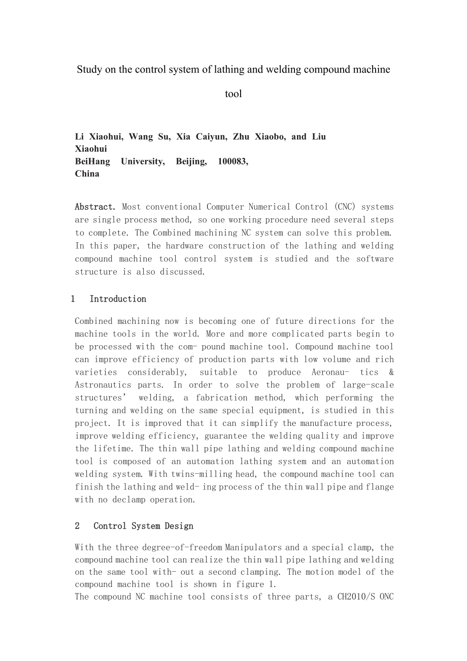

《机械方向毕设外文翻译》由会员分享,可在线阅读,更多相关《机械方向毕设外文翻译(12页珍藏版)》请在装配图网上搜索。
1、Study on the control system of lathing and welding compound machine toolLi Xiaohui, Wang Su, Xia Caiyun, Zhu Xiaobo, and Liu XiaohuiBeiHang University, Beijing, 100083, ChinaAbstract. Most conventional Computer Numerical Control (CNC) systems are single process method, so one working procedure need
2、several steps to complete. The Combined machining NC system can solve this problem. In this paper, the hardware construction of the lathing and welding compound machine tool control system is studied and the software structure is also discussed.1 IntroductionCombined machining now is becoming one of
3、 future directions for the machine tools in the world. More and more complicated parts begin to be processed with the com- pound machine tool. Compound machine tool can improve efficiency of production parts with low volume and rich varieties considerably, suitable to produce Aeronau- tics & Astrona
4、utics parts. In order to solve the problem of large-scale structures welding, a fabrication method, which performing the turning and welding on the same special equipment, is studied in this project. It is improved that it can simplify the manufacture process, improve welding efficiency, guarantee t
5、he welding quality and improve the lifetime. The thin wall pipe lathing and welding compound machine tool is composed of an automation lathing system and an automation welding system. With twins-milling head, the compound machine tool can finish the lathing and weld- ing process of the thin wall pip
6、e and flange with no declamp operation.2 Control System DesignWith the three degree-of-freedom Manipulators and a special clamp, the compound machine tool can realize the thin wall pipe lathing and welding on the same tool with- out a second clamping. The motion model of the compound machine tool is
7、 shown in figure 1.The compound NC machine tool consists of three parts, a CH2010/S ONC system made by BUAA as the control system, a corresponding AC motor and a photoelectric encoder as the executive component and the reactive component of servo system. NC device of the control system compiles of t
8、he program and sends order to the servo system, and then the servo system controls the motors movement. In the whole movement process, the photoelectric encoder mounted on the corresponding AC mo- tor detects the displacement and velocity of the compound machine tool, and this information is feed ba
9、ck to controller by the feedback system. After comparing the actual displacement and velocity with the target value and other information, the controller sends new orders to the corresponding AC motor to produce corresponding movement which can rectify the movement of the compound machine tool 1. It
10、 is a real-time detection, feedback and closed loop control system. The whole control structure of the lathing and welding compound NC machine tool is shown in figure 2.Fig. 1. Motion model of the compound machine toolFig. 2. The whole control structure of the machine tool3 Hardware ConstructionsThe
11、 hardware part is composed of a CH-2010/S control system, an AMK AC servo module and 8 induction AC servo motors. The CH-2010/S control system is an open controller system which is based on the PC computer and field bus SERCOS technology, and its hardware construction contains two cards, one is the
12、PC main- board card, another is the SERCOS-Master card. NC-PLC kernel operates the SERCOS-Master interface card with SERCOS-Master driver program and the SERCOS-Master card connects with the AMK AC servo module. The AMK AC servo module is used as the control module. The AMK-AZ sends signals to AMK-
13、AW when any numeric control command receives from SERCOS. And then the AMK-AW exports the signals to three phase induction AC servo motors. The hardware construction of the control system is shown in figure 3.Fig. 3. Hardware construction of control systemThe SERCOS-Master card has the machine tool
14、operation buttons, multiple switch and hand wheel port which are available for all kinds of NC machine tools. The CH-2010/S controls the machine tool control module with the SERCOS-Master card, which is composed of 150 SERCOS feed stages and 40320 PLC-IO ports. The hardware hookup of the control sys
15、tem is shown in Figure 4. In this figure the AW# means AMK servo module, M# means the number of motor, AM# means the coder relative to motor, and SB# indicates located restrictive switch of the machine tool.4 Software ConstructionsAll kinds of resources provided by the WINDOWS operating system can b
16、e used conveniently in the CH-2010/S. It offers the software application environment and a group of normal system performance functions to users, such as: 231. The Manipulative Performance, including the manipulative menu, coordinate display, operating states display and graphical display etc.2. Dat
17、a Management System, including system parameters, tools data, NC programs, files and table edit.3. System Soft Interface, sending the NC variable, NC data and PLC variable to theNC-PLC kernel and reading them from it.With the NC variable, NC data and PLC variable, the commands and data are transferr
18、ed between the CNC system software and application software. NC variable is used for sending control orders such as the selection of work type, cycle starting, feeding keeping and reset operation etc from application software to NC kernel, or reading the machine tool coordinate and the NC kernel wor
19、k states from the NC kernel. The NC data include the NC program, tool data and machine tool parameters etc. Using the PLC variable, the orders can be sent to the PLC kernel from application software straightway and the information of PLC kernel can be read. The PLC kernel offers plenty blending func
20、tion for invoking. The NC software environment of the CH2010/S is shown in figure 4.Fig. 4. CH2010/S NC software environmentBased on object-oriented technology, in the open CNC software, the control sys- tem is divided into many functional modules to accomplish different functions. The C/S module is
21、 used for transferring the information between modules and control sys- tem kernel or different modules 46. The module offering service function is the server module and the module asking for the function service is client module.For the scalability, maintainability and reconfiguration of CNC system
22、 software, the software is designed with modular method. Based on the control system function, different modules are designed for multi-task ability of control system. The main control module should accomplish many complex tasks, such as the initialization, the NC program input, edit compiling, sett
23、ing parameters and operation. So it is needed to design a series of unattached function program modules, and furthermore, the same program module has the different module contents under the different control methods.The control program is designed based on the Windows operating system, so it has the
24、 multi-task coordinated ability. In the program, user manipulative performance is composed of many windows and each of them executes one task. And the functions are realized competitively in the different windows. The states of each task are managed by the management program 56. The main function of
25、 main-menu performance is monitoring, performance management, function controlling and system managing.The control part is the vital part of the whole software, and it determines the qualification of the control system. The flow chat of the whole software is shown in fig.7. After initialization of t
26、he system, the reference point setting and etc., the SERCOS- Masters drivers can be used for operating its interface card. And SERCOS-Master interface card supplies the difference interpolation functions which are available for movement control.5 MeasurementPositioning accuracy of the machine tool s
27、ix axes are measured by ML10 laser interferometer made by the Renishaw Company. The measurement results are analyzed by the corresponding analysis software. The following results are obtained.jiOverall Accuracy, A = Max (x x).Positive Repeatability Accuracy, pos rep=max pos-min pos.Reverse Repeatabi
28、lity Accuracy, rev rep=max rev-min revBidirectional Repeatability Accuracy B= x x The analysis results are shown in table 1. The max overall accuracy is 301.8m, the max positive repeatability is 277.4m, the max reverse repeatability is 150.7m, and the bidirectional repeatability is 367.6m. From the
29、results it is found that the control system can satisfy the machine tools accuracy request.Table 1. Positioning accuracy of six axesmotion axesOverallAccuracy(m)PositiveRepeatability(m)ReverseRepeatability(m)BidirectionalRepeatability(m)X axis156.264.7141.9Y axis251.520.920.934.8Z axis39.147.8367.6U
30、 axis301.8245.5150.7264.7V axis264277.437.4345.3W axis39.147.8307.66 Conclusions1. Based on the CH-2010, the control system of the lathing and welding compound NC machine tool is designed, which has many fine characteristics, such as good expansibility, general-purpose functions and friendly user in
31、terface.2. Multiple machine axes are moved simultaneously, and the control system can realize the auto control of the lathing and welding processing. It can satisfy the lathing and welding combined machining require.3. The control system can realize Off-line Programming and test show that the system
32、 run credibility and can fulfill the control accuracy requirement.中文翻译关于车削加工和焊接加工复合机床的控制系统的研究摘要,很多的计算机数控(CNC)系统是单进程的方法,所以一工序需要几个步骤来完成。该复合加工数控系统可以解决这个问题。在这篇论文中,对车削和焊接复合加工机床控制系统的硬件结构和软件结构的研究进行了讨论。1, 介绍复合加工现在正成为世界机床未来发展的方向之一,伴随着复合机床的产生,越来越多的复杂零件开始得以加工。复合加工机床可以提高小件生产的效率和大量的增加工件种类,适合生产航空航天部件。为了解决大件结构的焊接问
33、题,在这个项目中,正在研究一种在一个专用机床上可以车削和焊接加工的方法。这是改进,它可以简化生产工艺,提高焊接效率,保证焊接质量,提高寿命。薄壁管的车削加工和焊接复合机床由一个自动化车削加工工艺系统以及一个自动化的焊接系统组成。带有双胞胎铣头,复合机床能完成薄壁管件及需加紧法兰的车削加工工艺和焊接加工。2,控制系统设计带有三个自由度机械手及一个特殊的复合机床夹具,复合机床可以实现车削加工工艺和焊接薄壁管在相同的工具,而不需要第二个装夹。复合机床的运动模型如图1所示。图1,复合机床的运动模型 这个复合数控机床是由三部分组成,一个由北航设计的CH2010/S的开放式控制系统,一个相应的交流电机和作
34、为执行元件和伺服系统的无功组成部分的光电编码器, 数控设备控制系统的编译程序和发送顺序给伺服系统,然后,伺服系统控制电机的运动。在整个运动过程中, 安装在相应的交流电动机上的光电编码器检测复合机床位移和速度, 而这个信息则反馈给反馈系统的控制器。通过与目标值以及其他信息比较实际位移和速度, CH2010/S数控系统 AMK-AZ控制单元车削交流电动机焊接交流电动机焊接加工车削加工车削反馈焊接反馈伺服系统SERCOS通信图2,车床的真个控制机构该控制器发送新命令到相应的交流电机产生相应的运动,它就能纠,正该复合机运动了。这是一种实时检测、反馈和闭环控制系统,车削加工工艺和焊接复合数控机床的整个控
35、制结构如图2所示。3硬件机构硬件部分由一个CH-2010 / S控制系统,一个AMK交流伺服模块和8个感应交流伺服电机。CH-2010 / S的控制系统是一个带有SERCOS(serial real time communication specification,串行实时通信协议)主站驱动程序的SERCOS接口卡,这个SERCOS主站和AMK交流伺服模块连接. AMK交流伺服系统的模块,是用来作为控制模块。当接收到SERCOS任何数字命令时,AMK-AZ就发信号到AMK-AW, 然后AMK-AW出口信号到三相异步交流伺服电机,控制系统的硬件框架如图3。图3控制系统的硬件框架这SERCOS主板
36、卡上有机床操作按钮,多路开关和手轮端口,这样可以操作各种类型的数控机床,这个CH-2010 / S控制系统控制机床上带有SERCOS主板卡的控制模块,这个模块是由150进给阶段和40320 PLC-IO(可编程控制 输入输出)站组成的。4软件结构视窗操作系统所提供的各类资源可以方便地用于CH-2010 / S。它为用户提供了软件应用环境和一组正常系统性能的功能,比如:1, 操作性能,包括操纵菜单,协调显示,操作状态显示和图形显示等。2, 数据管理系统,包括系统参数,工具-数据、数控加工程序,文件,表编辑。3, 系统界面,发送数控变量,数控数据和可编程序控制器(PLC)的变量到数控-可编程控制的
37、内核,并读取。带有这些数控变量、数控数据和可编程序控制器(PLC)变量,命令和数据会在计算机数控系统软件和应用软件之间传送。数控变量是用来发送控制命令的例如选择工作类型,循环开始,进给保持和复位操作系统等一些由应用软件到内核操作,或者从数控内核中读取机床坐标和数控内核的工作状态。数控的数据包括数控程序、工具数据和机床参数等。采用PLC全程序控制变量,该命令可以从应用软件送到PLC的内核,而且可编程序控制器(PLC)内核的信息可以去读取。可编程序控制器(PLC)的内核为调用提供了许多的混合功能。CH2010/S的数控软件环境如图4所示。基于面向对象的技术,在开放式数控系统的控制软件中,控制系统被
38、分割成许多功能模块来完成不同的功能。这个C / S模块是用来传递模块和控制系统内核或者不同模块间的信息。这个模块提供的服务功能是服务器模块,这个需要服务的模块称之为客户端模块。为了计算机数控系统软件的可扩展性、可维护性和重组的,该软件以模块化的方法设计。基于控制系统功能的基础上,不同的模块设计是为控制系统的多项任务能力主要控制模块应该完成许多复杂的任务,例如初始化,数控加工程序的输入,编辑编译,设置参数和操作。因此,必须设计一系列的独立的功能模块,而且,相同程序的模块在不同的控制方法下会有不同的内容。图4CH2010/S的数控软件环境应用软件系统操作性能用户操作性能用户控制功能 窗口应用程序系
39、统软件NC内核PLC内核SERCOS驱动NC0NC1NC xNC变量NC数据PLC数据1轴2轴X轴控制程序是基于视窗操作系统设计的,因此它具有协调多任务的能力。在程序中,用户的操纵性能由许多窗口组成的,而且每个窗口只执行一项任务。在不同的窗口中竞争性的实现功能,每项任务的状态都是由56管理程序控制的。主菜单的主要功能是监控、绩效管理、功能控制和系统管理控制部分是整个软件至关重要的一部分,它决定了控制系统的质量。在系统的初始化后,参考点的设置等之后,SERCOS主板驱动就能操作界面卡,同时SERCOS-Master界面卡提供不同的插值函数,这些函数能够用于运动控制。 5 测量 机床六个轴的位置精
40、度是通过雷尼绍公司制造的ML10激光干涉仪测量的,所测得的结果由相应的分析软件进行了分析,能够得到以下结果:总精度 A= Max(x, x )正向重复精度 pos rep=max pos-min pos 反向重复精度 rev rep=max rev-min rev双向重复精度 B=X-X分析结果显示在表1。mmmm,从结果发现,该控制系统能满足机床的精度要求。表1六个轴的位置精度运动轴总精度(m)正向精度(m)反向精度(m)双向精度(m)X轴156.264.7141.9Y轴251.520.920.934.8Z轴39.147.8367.6U轴301.8245.5150.7264.7V轴264277.437.4345.3W轴39.147.8307.61,基于CH-2010,车削加工和焊接复合数控机床设计的控制系统,具有许多优良特性,例如良好的可扩展性,通用功能和人性化的用户界面。2,多轴同时运动的时候,控制系统可实现自动控制车削加工和焊接加工,它能满足车削加工和焊接组合加工的要求。3,该控制系统能实现离线编程和测试表明该系统运行的可信度和精度能满足控制精度要求。 作者李晓辉,王苏,夏彩云,朱晓波,刘晓辉 北京航天航空大学
- 温馨提示:
1: 本站所有资源如无特殊说明,都需要本地电脑安装OFFICE2007和PDF阅读器。图纸软件为CAD,CAXA,PROE,UG,SolidWorks等.压缩文件请下载最新的WinRAR软件解压。
2: 本站的文档不包含任何第三方提供的附件图纸等,如果需要附件,请联系上传者。文件的所有权益归上传用户所有。
3.本站RAR压缩包中若带图纸,网页内容里面会有图纸预览,若没有图纸预览就没有图纸。
4. 未经权益所有人同意不得将文件中的内容挪作商业或盈利用途。
5. 装配图网仅提供信息存储空间,仅对用户上传内容的表现方式做保护处理,对用户上传分享的文档内容本身不做任何修改或编辑,并不能对任何下载内容负责。
6. 下载文件中如有侵权或不适当内容,请与我们联系,我们立即纠正。
7. 本站不保证下载资源的准确性、安全性和完整性, 同时也不承担用户因使用这些下载资源对自己和他人造成任何形式的伤害或损失。
