 外文翻译-冲压模具的受力分析

《外文翻译-冲压模具的受力分析》由会员分享,可在线阅读,更多相关《外文翻译-冲压模具的受力分析(20页珍藏版)》请在装配图网上搜索。
1、附录A 外文文献Stress Analysis of Stamping Dies作者:R. S. Rao 来源: Journal of Materials Shaping Technology发表时间: 1989-06-15 数据库 Springer期刊Abstract: Experimental and computational procedures for studying deflections, flit, andalignment characteristics of a sequence of stamping dies, housed in a transfer press,
2、are pre-sented. Die loads are actually measured at all the 12 die stations using new load monitors and used as input to the computational procedure. A typical stamping die is analyzed using a computational code, MSC/NASTRAN, based on finite element method. The analysis is then extended to the other
3、dies, especially the ones where the loads are high. Stresses and deflections are evaluated in the dies for the symmetric and asymmetric loading conditions. Based on our independent die analysis, stresses and deflections are found to be reasonably well within the tolerable limits. However, this situa
4、tion could change when the stamping dies are eventually integrated with the press as a total system which is the ultimate goal of this broad research program. INTRODUCTION Sheet metal parts require a series of operations such as shearing , drawing , stretching , bending , and squeezing. All these op
5、erations are carried out at once while the double slide mechanism descends to work on the parts in the die stations, housed in a transfer press 1. Material is fed to the press as blanks from a stock feeder. In operation the stock is moved from one station to the next by a mechanism synchronized with
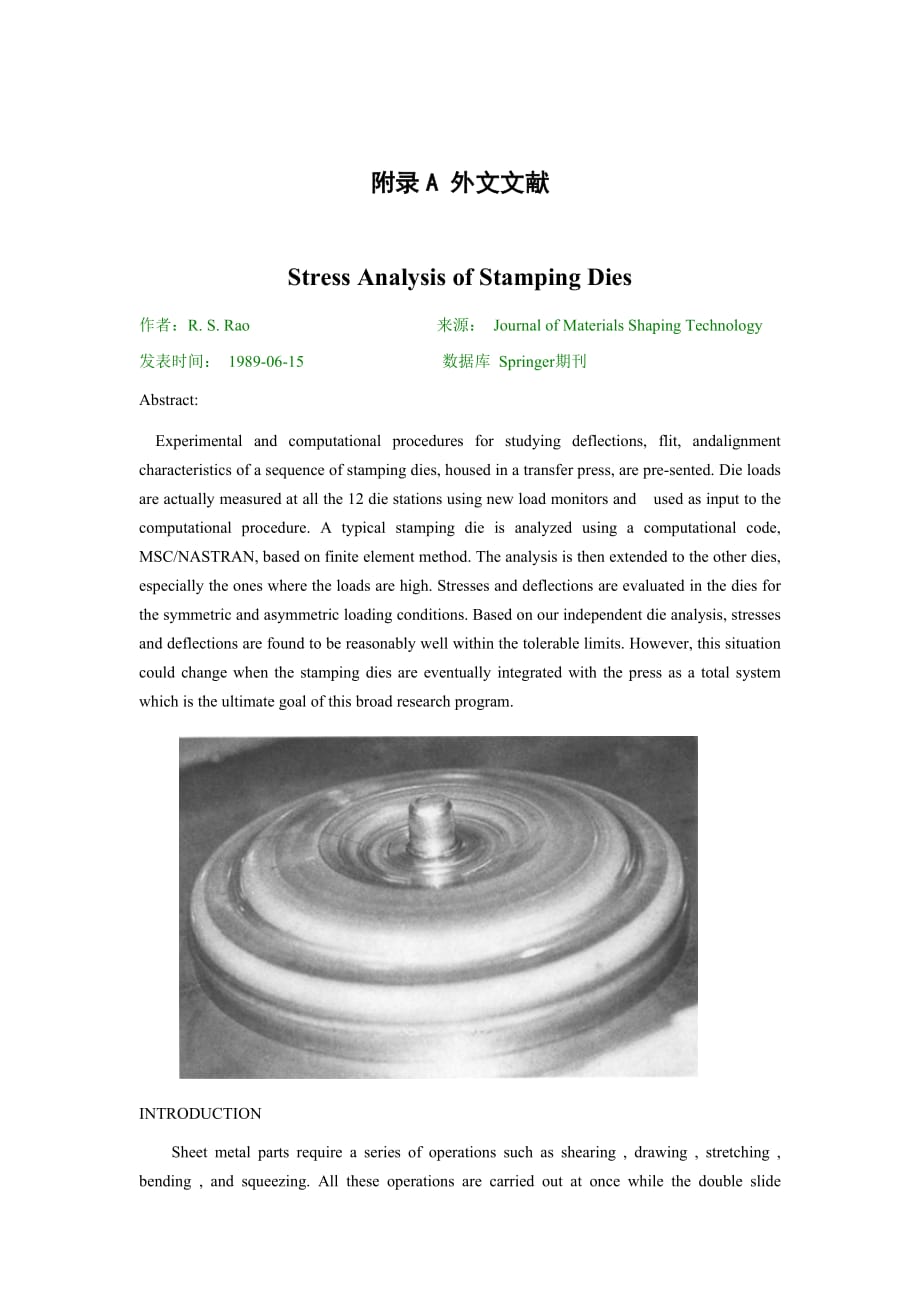
6、 the motion of the slide. Each die is a separate unit which may be independently adjusted from the main slide. An automotive part stamped from a hot rolled steel blank in 12 steps without any intermediate anneals is shown in Figure 1. Transfer presses are mainly used to produce different types of au
7、tomotive and aircraft parts and home appliances. The economic use of transfer presses depends upon quantity production as their usual production rate is 500 to 1500 parts per hour 2. Although production is rapid in this way, close tolerances are often difficult to achieve. Moreover, the presses prod
8、uce a set of conditions for off-center loads owing to the different operations being performed simultaneously in several dies during each stroke. Thus, the forming load applied at one station can affect the alignment and general accuracy of the operation being performed at adjacent stations. Another
9、 practical problem is the significant amount of set-up time involved to bring all the dies into proper operation. Hence, the broad goal of this research is to study the structural characteristics of press and dies combination as a total system. In this paper, experimental and computational procedure
10、s for investigating die problems are presented. The analysis of structural characteristics of the transfer press was pursued separately 3. A transfer press consisting of 12 die stations was chosen for analysis. Typical die problems are excessive deflections, tilt, and misalignment of the upperand lo
11、wer die halves. Inadequate cushioning and offcenter loading may cause tilt and misalignment of the dies. Tilt and excessive deflections may also be caused by the lack of stiffness of the die bolster and the die itself. Part quality can be greatly affected by these die problems. There are a lot of ot
12、her parameters such as the die design, friction and lubrication along the die work interface, speed, etc. that play a great role in producing consistently good parts. Realistically, the analysis should be carded out by incorporating the die design and the deforming characteristics of the work materi
13、al such as the elastic-plastic work hardening properties. In this preliminary study, the large plastic deformation of the workpiece was not considered for the reasons mentioned below. Large deformation modeling of a sheet stretching process was carded out using the computational code based on an ela
14、stic-plastic work hardening model of the deformation process 4. Laboratory experiments were conducted on various commercial materials using a hemispherical punch. The coefficient of friction along the punch-sheet interface was actually measured in the experiment and used as a prescribed boundary to
15、the numerical model. Although a good solution was obtained, it was realized that the numerical analysis was very sensitive to the frictional conditions along the interface. In the most recent work, a new friction model based on the micromechanics of the asperity contact was developed 5. In the prese
16、nt problem, there are several operations such as deep drawing, several reduction drawing operations, and coining, which are performed using complex die geometries. The resources and the duration of time were not adequate to study these nonlinear problems. Hence,the preliminary study was limited to d
17、ie problems basedon linear stress analysis. A detailed die analysis was carried out by using MSC /NASTRAN code based on finite ele mentmethod. Die loads were.measured at all the stations using new load monitors. Such measured data were used in the numerical model to evaluate stresses and deflections
18、 in the dies for normal operating conditions and for asymmetric loading conditions. Asymmetric loading conditions were created in the analysis by tilting the dies. In real practice, it is customary to pursue trial-and-error procedures such as placing shims under the die or by adjusting the cushion p
19、ressure to correct the die alignment problems. Such time consuming tasks can be reduced or even eliminated using the computational and experimental procedures presented here. DIE GEOMETRY AND MATERIALS The design of metal stamping dies is an inexact process. There are considerable trial-and-error ad
20、justments during die tryout that are often required to finish the fabrication of a die that will produce acceptable parts. It involves not only the proper selection of die materials, but also dimensions. In order to withstand the pressure, a die must have proper cross-sectional area and clearances.
21、Sharp comers, radii, fillets, and sudden changes in the cross section can have deleterious effects on the die life. In this work, the analysis was done on the existing set of dies. The dies were made of high carbon, high chromium tool steel. The hardness of this tool steel material is in the range o
22、f Rockwell C 57 to 60. Resistance to wear and galling was greatly improved by coating the dies with titanium nitride and titanium carbide. The dies were supported by several other steel holders made of alloy steels such as SAE 4140. The geometry of a typical stamping die is axisymmetric but it varie
23、s slightly from die to die depending on the operation. Detailed information about geometry andmaterials of a reduction drawing die (station number 4) was gathered from blueprints. It was reproducedin three-dimensional geometry using a preprocessor, PATRAN. One quadrant of the die is shown in Figure2
24、. The data including geometry and elastic properties of the die material were fed to the numerical model. The work material used was hot rolled aluminumkilled steel, SAE 1008 A-K Steel and the blank thickness was about 4.5 ram. Stampings used in unexposed places or as parts of some deisgn where fine
25、 finish is not essential are usually made from hot rolled steel. The automotive part produced in this die set is a cover for a torque converter. A principal advantage of aluminum-killed steel is its minimum strain aging.EXPERIMENTAL PROCEDURES As mentioned earlier, this research involved monitoting
26、of die loads which were to be used in the numerical model to staldy the structural characteristicsof dies. The other advantage is to avoid overloadingthe dies in practice. Off-center loading can be detected and also set-up time can be reduced. Thus, any changes in the thickness of stock, dulling of
27、the die,unbalanced loads, or overloadings can be detected using die load monitors. Strain gage based fiat load cells made of high grade tool steel material were fabricated and supplied by IDC Corporation. Four identical load cells were embedded in a thick rectangular plate as shown in Figure 3. They
28、 were calibrated both in the laboratory and in the plant.The plate was placed on the top of the die. The knockout pin slips through the hole in the plate. Six such plates were placed on each of six dies. In this way,24 readings can be obtained at a given time. Then they were shifted to the other six
29、 dies for complete data. All the 12 die loads are presented in Table 1.COMPUTATIONAL PROCEDURES Linear static analysis using finite element method wasused to study the effect of symmetric and asymmetric loading for this problem. A finite element model of die station 4 was created using the graphical
30、 preprocessor, PATRAN, and the analysis was carried outusing the code MSC/NASTRA N . The code has a wide T a b l e I. Die LoadsDie Station LoadNumber (kN)1 3562 6413 2144 3565 8546 7127 2858 32O9 234910 113911 21412 2100spectrum of capabilities, of which linear static analysis is discussed here. The
31、 NASTRAN code initially generates a structural matrix and then the stiffness and the mass matrices from the data in the input file. The theoretical formulations of a static structural problem by the displacement method can be obtained from the references 6. The unknowns are displacements and are sol
32、ved for the appropriate boundary conditions. Strains are obtained from displacements. Then they are converted into stresses by using elastic stress-strain relationships of the die material. The solution procedure began with the creation of die geometry using the graphical preprocessor, PATRAN. The s
33、olution domain was divided into appropriate hyper-patches. This was followed by the generation of nodes, which were then connected by elements. Solid HEXA elements with eight nodes were used for this problem. The nodes and elements were distributed in such a way that a finer mesh was created at the
34、critical region of the die-sheet metal interface and a coarser mesh elsewhere. The model was then optimized by deleting the unwanted nodes. The element connectivities were checked. By taking advantage of the symmetry, only one quarter of the die was analyzed. In the asymmetric case, half of the die
35、was considered for analysis. Although, in practice, the load is applied at the top of the die, for the purpose of proper representation of the boundary conditions to the computational code, reaction forces were considered for analysis. The displacement and force boundary conditions are shown for the
36、 two cases inFigure 4.As mentioned earlier, sheet metal was not modeled in this preliminary research. As shown in Figure 4(a),the nodes on the top surface of the die were constrained (stationary surface) and the measured load of 356 kN was equally distributed on the contact nodes at the workpiece di
37、e interface. Similar boundary conditions for the punch are shown in Figure 4(b). It is noticeable that fewer nodes are in contact with the sheet metal due to the die tilt for the asymmetric loading case as shown in Figure 4(c). In real practice, the pressure actually varies along the die contact sur
38、face. Since the actual distribution was not known, uniform distribution was considered in the present analysis.DISCUSSION OF RESULTS As described in the earlier section, the numerical analysis of die Station 4 (both the die and punch) was performed using the code MSC/NASTRAN . Two cases were conside
39、red, namely: (a) symmetric loading and (b) asymmetric loading Fig. 4. Boundary conditions. (A) Symmetric case (onequadrant of the die). (B) Symmetric case (one quadrant ofnthe punch). (C) Asymmetric case (half of the die).Symmetric Loading Numerical analysis of the die was carried out for a measured
40、 load o f 356 kN as distributed equally in Figure 4(a). The major displacements in the loading direction are shown in Figure 5(a). These displacement contours can be shown in various colors to represent different magnitudes. The m aximum displacement value is 0.01 m m for a uniformly distributed loa
41、d of 356 kN. The corresponding critical stress is very small, 8.4 MPa in the y direction and 30 MPa in the x direction. The calculated displacements and stresses at the surrounding elements and nodes wereof the same order, but they decreased in magnitude at the nodes away from this critical region.
42、Thus, the die was considered very rigid under this loading condition. Symmetric loading was applied to the punch and the numerical analysis was carried out separately. The displacement values in the protruding region of the punch were high compared to the die. The maximum displacement was 0.08 m m .
43、 It should be noted that the displacement values in this critical range of the punch were of the same order ranging from 0.05 mm to 0.08 ram. Although the load acting on the punch (bottom half) was the same as the die (upper half), that is, 356 kN, the values of displacements and stresses were highe
44、r in the punch because of the differences in the geometry. This is especially true for the protruding part of the punch. The corresponding maxim u m stress was 232 MPa. This part of the punch is still in the elastic range as the yield strength of tool steel is approximately 1034 MPa. The critical st
45、ress value might be varied for different load distributions. Since the actual distribution of the load was not known,the load was distributed equally on all nodes. As the die (upper half) is operating in a region which is extremely safe, a change in the load distribution may not produce any high cri
46、tical stresses in the die. Although higher loads are applied at other die stations(see Table 1), it is concluded that the critical stresses are not going to be significantly higher due to the appropriate changes in the die geometries.Asymmetric Loading For the purpose of analysis, an asymmetric load
47、ing situation was created by tilting the die. Thus, only 15 nodes were in contact with the workpiece compared to 40 nodes for the symmetric loading case. As shown in Figure 4(c), a 356 kN load was uniformly distributed over the 15 nodes that were in contact with the workpiece. Although the pressure
48、was high, because of the geometry at the location where the load was acting, the critical values of displacement and stress were found to be similar to the symmetric case. The predicted displacement and stress values were not significantly higher than the values predicted for the symmetric case. Fig
49、. 5. Displacement contours in the loading direction. (A) Symmetric case (one quadrant of thedie). (B) Symmetric case (one quadrant of the punch). (C)Asymmetric case (half of the die).CONCLUSIONS In this preliminary study, we have demonstrated the capabilities of the computational procedure, based on
50、 finite element method, to evaluate the stresses and deflections within the stamping dies for the measured loads. The dies were found to be within the tolerable elastic limits for both symmetric and asymmetric loading conditions. Thus the computational procedure can be used to study the tilt and ali
51、gnment characteristics of stamping dies. In general, the die load monitors are very useful not only for analysis but also for on-line tonnage control. Future research involves theintegration of the structural analysis of stamping dies with that of the transfer press as a total system.ACKNOWLEDGMENTS
52、Professor J.G. Eisley, W.J. Anderson, and Mr. D.Londhe are thanked for their comments on this paper.REFERENCES1. R.S. Rao and A. Bhattacharya, Transfer Process De-flection, Parallelism, and Alignment Characteristics,Technical Report, January 1988, Department of Mechanical Engineering and Applied Mec
53、hanics, the University of Michigan, Ann Arbor.2. Editors of American Machinist, Metalforming: Modem Machines, Methods, and Tooling for Engineers and Operating Personnel, McGraw-Hill, Inc., 1982, pp. 47-50.3. W.J. Anderson, J.G. Eisley, and M.A. Tessmer,Transfer Press Deflection, Parallelism, and Ali
54、gnment Characteristics, Technical Report, January 1988, Department of Aerospace Engineering, the University of Michigan, Ann Arbor.4. B.B. Yoon, R.S. Rao, and N. Kikuchi, Sheet Stretching: A Theoretical Experimental Comparison, International Journal of Mechanical Sciences, Vol. 31, No.8, pp. 579-590
55、, 1989.5. B.B. Yoon, R.S. Rao, and N. Kikuchi, Experimental and Numerical Comparisons of Sheet Stretching Using a New Friction Model, ASME Journal of Engineering Materials and Technology, in press.6. MSX/NASTRAN, McNeal Schwendler Corporation.22 9 J. Materials Shaping Technology, Vol. 8, No. 1, 1990
56、冲压模具的受力分析 R.S.Rao J.Mater.Shaping Technol 8:17-22 施普林格出版社纽约公司 文章摘要:我们用一台多工位自动压力机来研究冲压模具的变形过程,其中包括突然换位,校准特征等一系列的过程。模具载荷实验实际上是对12个工位使用新的负载监控后的测量(其测量的数值将会输入计算程序)。再基于有限元法对冲压模具进行分析(其中有限元法需要用到一个计算代码和MSC/NASTRAN分析软件)。这样后再将分析扩展到其他的模具,特别是那些高负载的冲模。应力和变形是用来评估模具载荷对称还是非对称的条件,根据我们对模具独立的分析发现在模具的应力和变形只要是轻度的那这个模具还是好
57、的。然而这种情况在当冲压模具最终和压力机成为一个整体后也是可能会变化的。简介: 钣金零件需要拉伸,剪切,弯曲,和挤压等一系列的操作,所有这些操作的进行都会被安置在多工位自动压力机上。材料是通过给料机送入压坯,在操作中材料通过同步机制的滑块运动从一个位置运动到下一个位置。在生产中每一个模具都是一个独立的单位,其都可以在主滑动上进行单个调整。如图1所示一个用热轧钢板做的汽车零件其不需要退火的12个加工步骤。 图1:一个冲压零件 压力机主要用于生产不同类型的汽车和飞机零部件和家电,不同的多工位自动压力机其生产速率大约在500到1500每小时。虽然以这种速度生产是快速的,但往往紧密的公差尺寸很难实现。
58、此外,机器在每个冲程中在偏心载荷的作用下同时在几个模具上进行不同的操作,因此,在某一个位置上的冲压载荷会影响工作线上其他操作的执行。另外一个实践问题就是把所有的模具正确的安装到压力机上的大量的时间问题。因此,本研究的目标是研究当压力机和模具联合作为一个整体时结构特点。在本文中,将会展示那些研究模具问题的实验和计算过程,还有单独对压力机结构特点的分析。 我们将会用一种由12个工位组成的压力机来分析。一般典型的模具问题有过度变形,倾斜,和上下半模错位,不适当的缓冲和偏心载荷会引起模具的倾斜和错位。倾斜和过度变形也可能是由模套与模具本身的刚度不足而造成的。这些模具问题将会对所生产的部分产品有很大的影
59、响。还有很多其他的参数,如模具设计,摩擦与润滑沿模具的工作界面的摩擦,速度,等等。这些问题的解决将会在生产中发挥很大的作用。实际上,分析应在结合模具设计及工作材料的变形特性下进行,譬如弹塑性的硬化加工。在这个研究中,工件的大面积塑性变形不作考虑。 大面积的拉伸变形过程是由于对建模过程的弹塑性硬化的计算代码的错误。实验室实验进行的各种商业材料使用的半球形冲头。沿穿孔板的界面摩擦系数实际上是在实验测量和作为边界的数值模型。虽然得到了很好的解决方案,实现了数值分析是沿界面摩擦条件非常敏感。在最近的工作中,一种新的基于细观接触摩擦模型被发明 5 。在目前的问题,在使用复杂的几何结构的模具,有几个操作如
60、拉深,少数减少的绘图操作,和模压。资源的持续时间都不足以研究这些非线性问题。因此,初步的研究仅限于模具基于线性应力分析问题。基于有限元方法通过利用MSCNASTRAN代码对模具进行了一个详细的分析。在所有使用新的负载监控站对模具载荷进行了测定。这样的测量数据运用在数值模型中来评估模具的正常工作条件下和非对称载荷状况的应力和变形。在模具倾斜中非对称载荷也是应被分析的。在实践中,人们习惯于追求的试验和错误的程序,如放置垫片在模具或调整垫压模对准正确的问题。这种耗时的任务,可以在这里提供的计算和实验程序减少甚至消除使用。模具的形状和材料 金属冲压模具的设计是一个不精确的过程。在试模中有相当多的试验和
61、错误,往往需要进行可接受的零件调整来完成一个模具。它不仅涉及到模具材料的正确选择,而且还有尺寸。为了能够承受压力,模具必须有适当的横截面积与间隙,半径,内圆角,和横截面的突变会对模具寿命产生有害的影响。在这项工作中,对模具的现有的设置进行了分析。 模具是用高碳,高铬工具钢做的。这个工具钢材料的硬度在罗克韦尔C 57至60的范围内。通过涂层模具氮化钛和碳化钛大大提高耐磨性。模具的制成还有其他几种合金钢如SAE 4140。一个典型的冲压模具的几何形状是轴对称的但根据操作不同每个模具也是有略微不同的。关于减少拉深模具的几何形状和材料的详细信息被收集于设计图中。通过使用一个预处理程序转载成3d几何图形
62、,Patran。一个象限的模具,如图2所示。数据包括模具材料的几何形状和模具的弹性性质。 所使用的工作材料是铝合金,SAE 1008,钢的厚度约为4.5的RAM。冲压件在阴暗的地方使用或一些不必要完好完成的部分通常是用热轧钢板来制作。该模具生产的汽车是一个变矩器盖。铝合金的主要优势是它的最小应变时效。实验程序 如前所述,本研究涉及数值模型中使用的模具载荷的监测,staldy模具的结构特点。另一个优点是避免模具在正式工作中超载。偏心加载可以被检测到,并设置时间可以减少。因此材料厚度的变化,模具的钝化,不平衡负载,或超载都可以使通过模具载荷监控方法检测。IDC公司提供了基于应变的菲亚特负载细胞制成
63、优质工具钢材料。四个相同的传感器被嵌入在一个厚矩形板,如图3所示。他们被校准在实验室和工厂。板被放置在模具的顶端。敲出来的销板中的孔滑过。六个这样的板被放置在每个模具上。在这种方式中,24个读数,可以在给定的时间内得到。然后他们通过完整的数据被转移到其他六个模具。所有12个模具载列于表1。 图2:模具的几何形状(一个象限) 图3:四个负载组镶嵌于一个厚的板料中计算程序 通过采用有限元方法的线性静态分析的方法研究了对称和非对称载荷的影响这一问题。通过使用图形处理器建立了模具站4有限元模型,Patran软件,在分析进行中使用代码MSC / NASTRAN。该代码具有广泛的功能,其中这里是关于其线性静力的分析讨论。
- 温馨提示:
1: 本站所有资源如无特殊说明,都需要本地电脑安装OFFICE2007和PDF阅读器。图纸软件为CAD,CAXA,PROE,UG,SolidWorks等.压缩文件请下载最新的WinRAR软件解压。
2: 本站的文档不包含任何第三方提供的附件图纸等,如果需要附件,请联系上传者。文件的所有权益归上传用户所有。
3.本站RAR压缩包中若带图纸,网页内容里面会有图纸预览,若没有图纸预览就没有图纸。
4. 未经权益所有人同意不得将文件中的内容挪作商业或盈利用途。
5. 装配图网仅提供信息存储空间,仅对用户上传内容的表现方式做保护处理,对用户上传分享的文档内容本身不做任何修改或编辑,并不能对任何下载内容负责。
6. 下载文件中如有侵权或不适当内容,请与我们联系,我们立即纠正。
7. 本站不保证下载资源的准确性、安全性和完整性, 同时也不承担用户因使用这些下载资源对自己和他人造成任何形式的伤害或损失。
